
Alkali metal thermal to electric converter system including heat exchanger

Inactive Publication Date: 2014-11-13
KOREA INST OF ENERGY RES
View PDF6 Cites 7 Cited by
  • Summary
  • Abstract
  • Description
  • Claims
  • Application Information

AI Technical Summary

Benefits of technology

The present invention provides a system for recycling without a temperature gradient through a heat exchanger and circulation of thermal fluid. This results in a very efficient system. Compared to conventional systems, the present invention has minimal temperature differences, reducing thermal shock and maintaining the performance of the cells in a constant state. The temperature difference between the system and the cooling part increases, allowing for efficient condensation and smooth circulation of the working fluid. This maximizes the system efficiency and allows for easy manufacturing of the heat exchanger in a compact form.

Problems solved by technology

However, the NASICON has a problem in its stability of crystal structure when it is exposed to high temperature for a long time.

Method used


Image

  • Alkali metal thermal to electric converter system including heat exchanger
  • Alkali metal thermal to electric converter system including heat exchanger
  • Alkali metal thermal to electric converter system including heat exchanger

Examples


Embodiment Construction

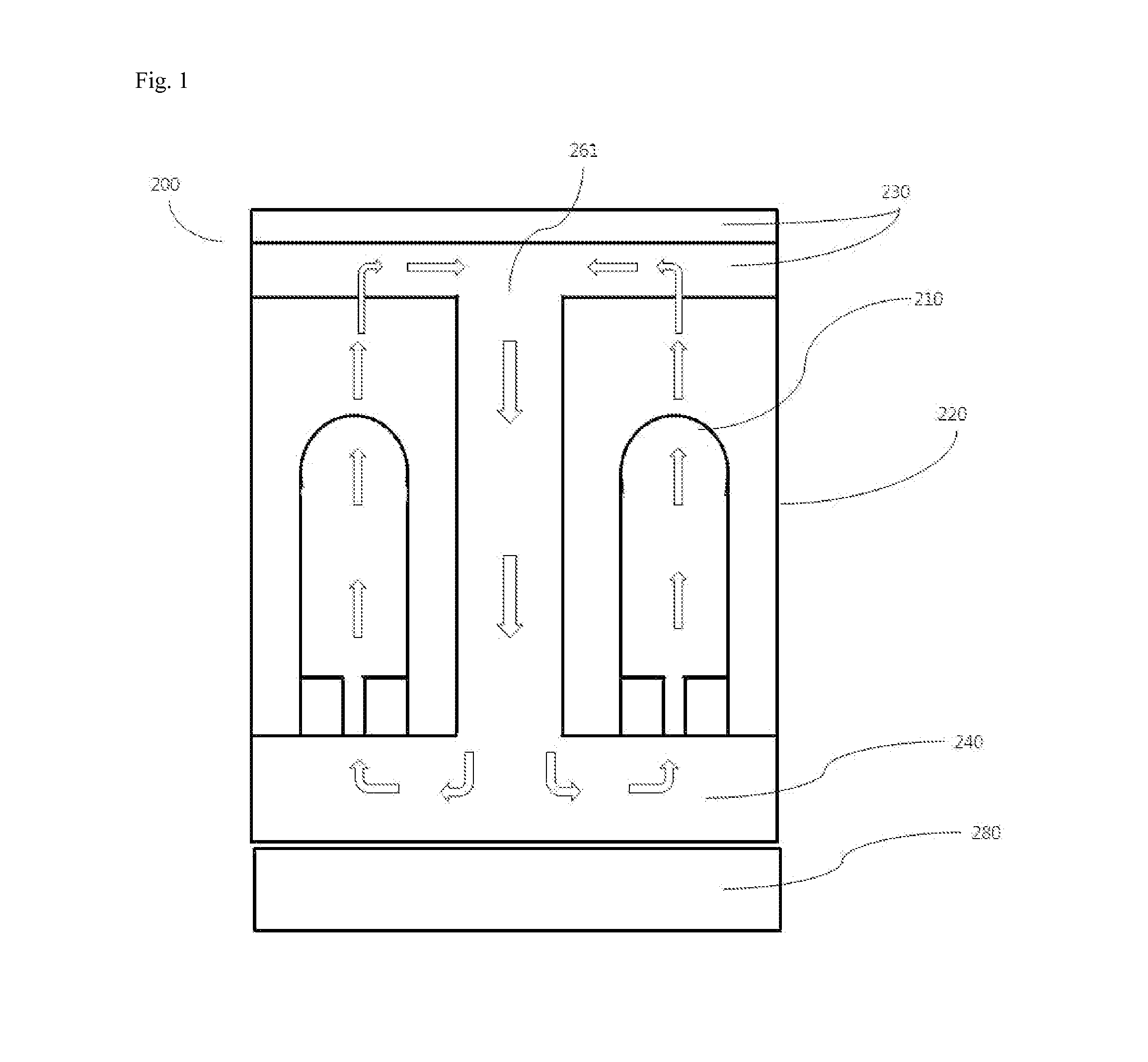
[0038]FIG. 3 is a diagram showing a principle of operation of a unit thermal to electric power generator in accordance with the present invention.

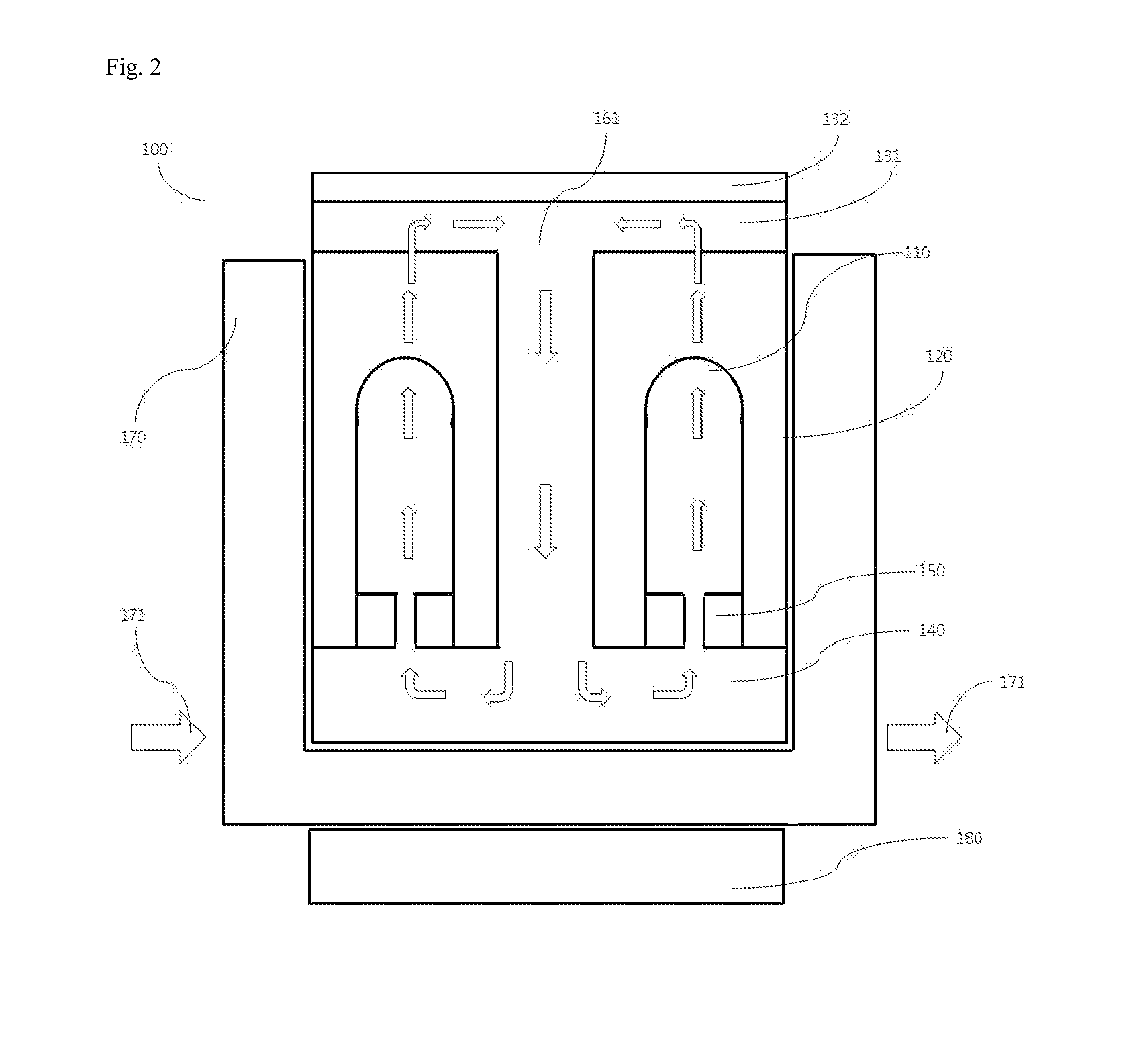
[0039]FIG. 2 is a diagram showing a principle of operation of a thermal to electric power generator including a heat exchanger in accordance with the present invention.

[0040]The present invention provides a thermal to electric power generator 100 including a plurality of thermal to electric power generation cells 110 including a heat exchanger. The thermal to electric power generator includes: a plurality of thermal to electric power generation cells 110; a case 120 in which the plurality of the thermal to electric power generation cells 110 are placed; a condensing unit 130 which is disposed on an upper portion of the case 120 and collects and condenses a working fluid which has passed through the plurality of the thermal to electric power generation cells 110; an evaporator 140 which is disposed on a lower portion of the case 120, conver...


PUM


Abstract

Disclosed is a thermal to electric power generator comprising: a plurality of thermal to electric power generation cells; a case in which the plurality of the thermal to electric power generation cells are placed; a condensing unit which is disposed on an upper portion of the case and collects and condenses a working fluid which has passed through the plurality of the thermal to electric power generation cells; an evaporator which is disposed on a lower portion of the case, converts the working fluid into vapor by transferring heat to the working fluid; a heat exchanger which is placed on a surface other than an upper surface of the outside of the case contacting with the condensing unit; a circulator which connects the condensing unit and the evaporator; and a joiner which joins the evaporator to the plurality of the thermal to electric power generation cells.

Description

BACKGROUND[0001]1. Field[0002]The present invention relates to a technology capable of maximizing efficiency by uniformly increasing the temperature of an AMTEC system which is driven by external heat and generates electricity and capable of continuously supplying required heat sources.[0003]2. Description of Related Art[0004]Alkali Metal Thermal to Electric Converter (AMTEC) is a thermal to electric power generator capable of generating electrical energy from thermal energy.[0005]When a temperature difference is given to both ends of an ionically conductive Beta-Alumina Solid Electrolyte (BASE), Na charged in the cell is ionized into Na+ due to the vapor pressure difference of Na and is diffused from anode to cathode through the electrolyte, and then is neutralized.[0006]In this case, low voltage and high current are generated. So, when the cells are modularized by being connected in series or in parallel, a large amount of electric power can be generated.[0007]The development of a...

Claims


Application Information

Patent Timeline
IPC IPC(8): H01G9/21
CPCH01G9/21F28D15/0266F28D15/04H02N3/00
Inventor KIM, SUN-DONGWOO, SANG-KUKKIM, SE-YOUNGJOO, JONG-HOONHAN, IN-SUBSEO, DOO-WONSUH, MIN-SOO
Owner KOREA INST OF ENERGY RES
Learn More