System and process for friction consolidation fabrication of permanent magnets and other extrusion and non-extrusion structures

Active Publication Date: 2014-11-06
BATTELLE MEMORIAL INST
View PDF3 Cites 20 Cited by
  • Summary
  • Abstract
  • Description
  • Claims
  • Application Information

AI Technical Summary

Benefits of technology

The patent describes a process for making a strong magnet by using an electromagnetic coil and a rotating containment die to create a magnetic field and align particles of magnet-forming material. An ultrasonic field can also be applied to further help align the particles. After consolidation, the permanent magnet is coated with a protective coating to prevent oxidization and corrosion. The technical effects are that the magnet has reduced energy loss and improved performance.

Problems solved by technology

While most of the rare earth elements are not rare, a shortage currently exists for some rare earth elements, in particular, neodymium (Nd) and dysprosium (Dy) due principally to world-wide demand for magnets used in motors and generators.
However, costs for manufacturing magnets in the U.S. are higher than those in China and Japan due to higher purchase prices for these rare earth elements and / or technology licensing costs.
Consequently, magnet manufacturing has largely moved from the U.S. Currently, there is concern in the U.S. that growth in wind-based power generation and electric vehicle technology, which require high-performance rare earth magnets, may be stifled by a lack of economically-competitive electric generators and motors because of the high cost of key magnetic components.
However, conventional powder metallurgy processes are both energy-intensive and time-intensive and often waste large amounts of materials during sizing and shaping.
And, these powder metallurgy processes also have limited ability to attain desired microstructure and bulk density values.
However, while the architecture of exchange-coupled nanocomposites has been worked out theoretically, technical challenges have prevented the theoretical concepts being put into practice.
However, conventional powder metallurgy involves several energy-intensive steps, so particles with sizes at or below 100 nm are not produced economically.
Further, conventional powder metallurgy does not generally achieve homogeneous mixing between the soft magnetic phase materials and the hard magnetic phase materials needed to produce a uniform exchange coupling.

Method used


Image

  • System and process for friction consolidation fabrication of permanent magnets and other extrusion and non-extrusion structures
  • System and process for friction consolidation fabrication of permanent magnets and other extrusion and non-extrusion structures
  • System and process for friction consolidation fabrication of permanent magnets and other extrusion and non-extrusion structures

Examples


example 1

Friction Consolidation and / or Extrusion as a Replacement to Conventional Sintering

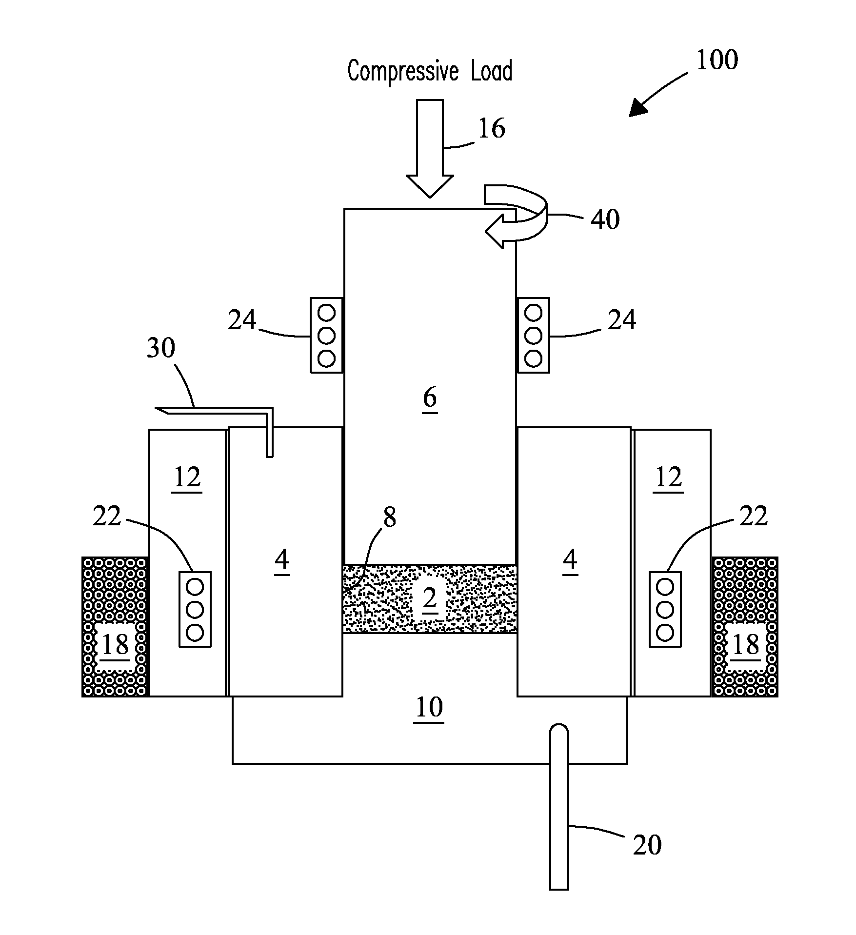
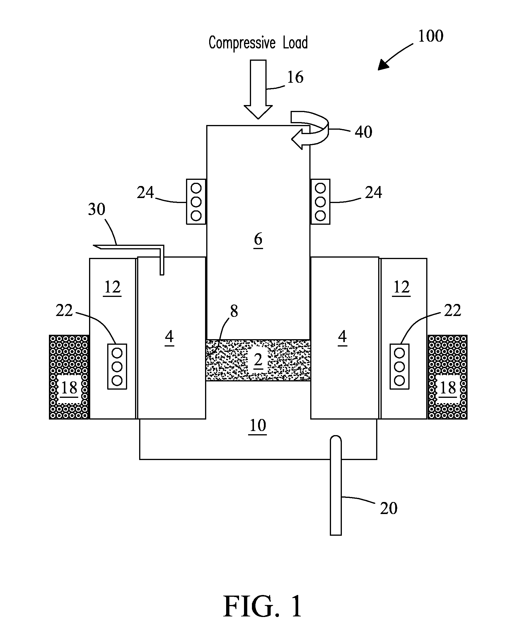
[0090]Feedstock particles were obtained by crushing and grinding melt-spun ribbons of Nd12.8Fe63.8BDy5.9Y6.4CO8.1Ti1.6C0.4. The die tool of FIG. 1 was used to frictionally consolidate the feedstock powder. A containment die with a 1-inch (2.54 cm) inner diameter was used. A plunge tool composed of tungsten rhenium (WRe) with a 1-inch (2.54 cm) outer diameter and a 6-inch (15.2 cm) length was used. About ˜50 gram of feedstock powder was introduced into the containment die. Chilled water was circulated inside the die fixture that secures the containment die at a temperature of 15° C. and a flow rate of 4 G / min (15.1 L / min). The plunge tool applied a compression load of 10,000 pound-force (lbf) to the feedstock powder in the containment die while rotating the feedstock powder at a rotation speed of 125 rpm for 125 seconds before disengaging. The resulting consolidated magnet was allowed to cool to room te...

example 2

Consolidation of SmCo5+Fe

[0097]SmCo5 powder (Catalog #42732) and iron (Fe) powder (Catalog #00170) were purchased commercially (Alfa Aesar, Ward Hill, Mass., USA). Powders were mixed in a weight ratio of [80:20]. Mixed powders were ball milled overnight at a rotation speed of 100 rpm to achieve homogeneity. The die tool of FIG. 1 was used to provide frictional consolidation of the SmCo5-Fe powder mixture. A containment die was used with a sample chamber with a 1-inch (2.54 cm) inner diameter. A plunge tool composed of a tungsten-rhenium (WRe) alloy with a 1-inch (2.54 cm) outer diameter (O.D.) and a 6-inch (15.2 cm) length was used. About ˜50 gram of feedstock powder was introduced into the containment die. No cooling to the containment die was provided. The plunge tool applied a compression load of 5,000 pound-force (lbf) to the feedstock powder in the containment die while rotating the feedstock powder at a rotation speed of 125 rpm for 30 seconds before disengaging. Since the are...

example 3

Consolidation of Nd12.8Fe63.8BDy5.9Y6.4Co8.1Ti1.6C0.4 Powder with Backward Extrusion

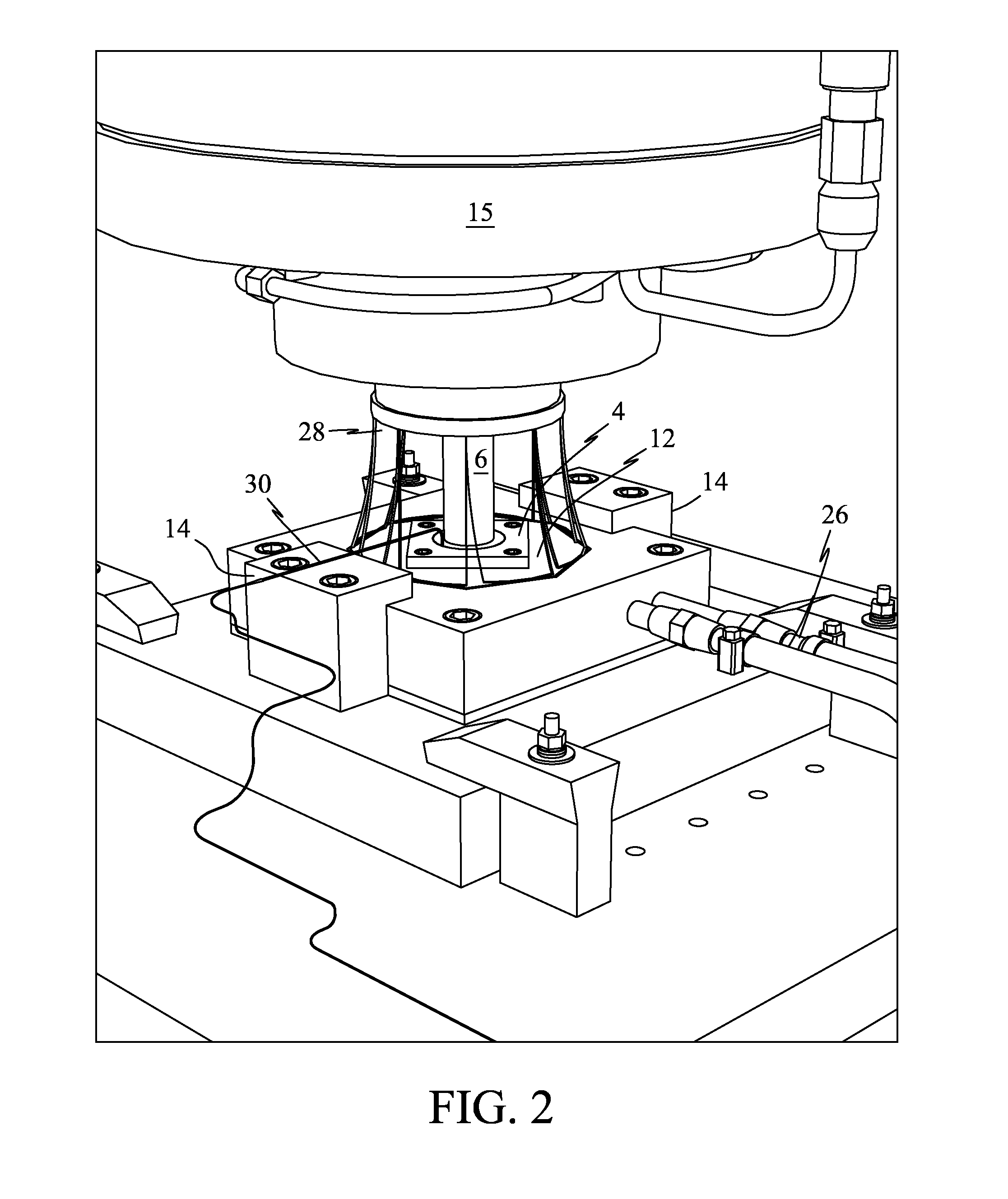
[0098]Feedstock powder was obtained by crushing and grinding melt-spun ribbons composed of Nd12.8Fe63.8BDy5.9Y6.4Co8.1Ti1.6C0.4. The die tool of FIG. 2 was used to consolidate the feedstock powder. A containment die was used with a sample chamber with a 1-inch (2.54 cm) inner diameter. A plunge tool made of an INCONEL® alloy (e.g., INCONEL® 718) was used with a 1-inch (2.54 cm) outer diameter and a 6-inch (15.2 cm) length. About ˜100 gram of feedstock powder was introduced into the chamber of the containment die. The plunge tool applied a compression load of 10,000 pound-force (lbf) to the feedstock powder while rotating the material at a speed of 125 rpm, which consolidated the feedstock powder. After consolidation, a new INCONEL® 718 plunge tool was installed that included a 1-inch (2.54 cm) outer diameter, a 6-inch (15.24 cm) length, and 0.2 inch (0.51 cm) extrusion hole. The new plunge tool appli...


PUM

PropertyMeasurementUnit
Temperatureaaaaaaaaaa
Fractionaaaaaaaaaa
Pressureaaaaaaaaaa

Abstract

A die tool and process are described that provide friction consolidation fabrication and friction consolidation extrusion fabrication products including permanent magnets, and other extrusion and non-extrusion structures. The present invention overcomes previous particle size, texture, homogeneity and density limitations in conventional metallurgy processes.

Description

CROSS REFERENCE TO RELATED APPLICATION[0001]This application claims priority from U.S. Provisional Application No. 61 / 819,291 filed 3 May 2013, which reference is incorporated herein in its entirety.STATEMENT REGARDING RIGHTS TO INVENTION MADE UNDER FEDERALLY-SPONSORED RESEARCH AND DEVELOPMENT[0002]This invention was made with Government support under Contract DE-AC05-76RLO-1830 awarded by the U.S. Department of Energy. The Government has certain rights in the invention.FIELD OF THE INVENTION[0003]The present invention relates generally to magnet manufacturing and extrusion tools and processes. More particularly, the invention includes a combined friction consolidation and extrusion die tool and process for fabrication of permanent magnets.BACKGROUND OF THE INVENTION[0004]A magnet is an energy-storage device. A magnet is energized when it is first magnetized. The energy remains in the magnet indefinitely when properly made and properly handled. Unlike batteries, magnetic energy is n...

Claims


Application Information

Patent Timeline
IPC IPC(8): H01F41/02
CPCH01F41/0266C22C19/07C22C38/002C22C38/005C22C38/10C22C38/14B29C43/04B29C43/34B29C43/361B29C43/52B29C43/56B29C2043/043B29C2043/3433B29C2043/3636B29C2043/568
Inventor CUI, JUNGRANT, GLENN J.JANA, SAUMYADEEPHOVANSKI, YURILAVENDER, CURT A.
Owner BATTELLE MEMORIAL INST
Why Eureka
Try Eureka