Liquid chromatograph apparatus and liquid chromatograph analysis method
- Summary
- Abstract
- Description
- Claims
- Application Information
AI Technical Summary
Benefits of technology
Problems solved by technology
Method used
Image

Examples
first embodiment
[0053]A first embodiment is described in which the operation timings are controlled on the basis of the operation of the liquid transfer pump with reference to FIGS. 3 and 4.
[0054]FIG. 3 is a flowchart for adjusting the timing of the start of liquid injecting operation by the liquid transfer pump according to the embodiment of the present invention.
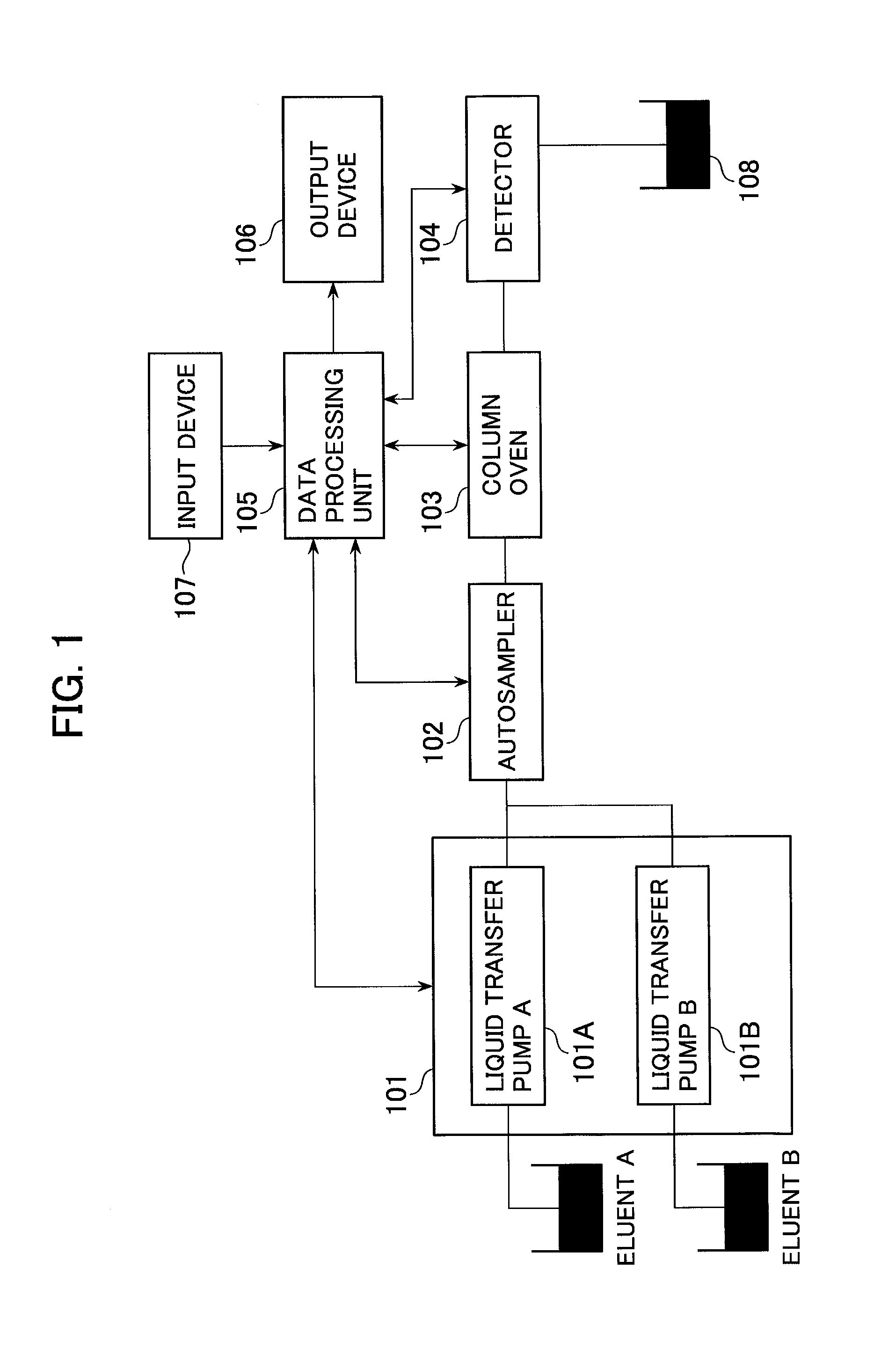
[0055]The liquid transfer pumps 101A, 101B need to obtain from respective sensors liquid transfer pressures used for drive control. An interval is set in which pressure data is not taken in for a given length of time (S301).
[0056]This interval is set at greater than the period in which the pressure of the transferred liquid varies due to the sample injecting operation from the liquid transfer pumps 101A and 101B or passage switching operation by the autosampler 102.
[0057]The output of synchronization signals from the liquid transfer pumps 101A and 101B is set so as to control functions which include the injecting operation and passage swi...
second embodiment
[0065]A second embodiment is described in which the timings of various operations are controlled on the basis of the operation of the autosampler with reference to FIG. 5.
[0066]FIG. 5 illustrates an operation flowchart for adjusting the timings of the sample injecting operation and passage switching operation of the autosampler according to the second embodiment of the present invention.
[0067]The autosampler 102 first receives information on an interval for obtaining liquid transfer pressure from the liquid transfer pump 101 (S501).
[0068]The output of synchronization signals from the liquid transfer pumps 101A and 101B are set so as to control functions including the sample injecting operation and passage switching operation of the autosampler 102 (S502).
[0069]After the setting of the above-mentioned items, the liquid transfer pumps 101A and 101B start liquid transfer operation (S503).
[0070]Unlike the first embodiment, the liquid transfer pumps 101A and 101B are driven at a fixed cy...
third embodiment
[0075]A third embodiment is described in which the data processing unit controls the various operation timings of the liquid transfer pump and the autosampler with reference to FIG. 6.
[0076]The data processing unit 105 first receives information on an interval for obtaining liquid transfer pressure from the liquid transfer pump 101 (S601).
[0077]The data processing unit 105 next sets the output of synchronization signals from the liquid transfer pumps 101A and 101B so as to control functions including the sample injecting operation and passage switching operation of the autosampler 102 (S602).
[0078]After the above-mentioned setting, the liquid transfer pumps 101A and 101B start liquid transfer operation (S603).
[0079]Unlike the first embodiment, the liquid transfer pumps 101A and 101B are driven at a fixed cycle. Specifically, the liquid transfer pumps 101A and 101B output synchronization signals to the data processing unit 105 at a position where a control phase is determined in a li...
PUM
 Abstract
Description
Claims
Application Information
 - R&D
- Intellectual Property
- Life Sciences
- Materials
- Tech Scout
- Unparalleled Data Quality
- Higher Quality Content
- 60% Fewer Hallucinations
Browse by: Latest US Patents, China's latest patents, Technical Efficacy Thesaurus, Application Domain, Technology Topic, Popular Technical Reports.
© 2025 PatSnap. All rights reserved.Legal|Privacy policy|Modern Slavery Act Transparency Statement|Sitemap|About US| Contact US: help@patsnap.com