
Aircraft environmental control system inlet flow control

Inactive Publication Date: 2014-10-16
HONEYWELL INT INC
View PDF1 Cites 12 Cited by
  • Summary
  • Abstract
  • Description
  • Claims
  • Application Information

AI Technical Summary

Benefits of technology

This patent describes an aircraft environmental control system that can regulate the flow of bleed air from a gas turbine engine into an air cycle machine, based on the temperature of the bleed air and conditioned air from the air cycle machine. This system includes an inlet flow control valve, an EGT sensor, a conditioned air temperature sensor, a controller, and other components. The technical effect of this invention is to provide a more efficient and precise means for controlling the flow of bleed air, which can improve the overall performance and efficiency of the aircraft's environmental control system.

Problems solved by technology

However, when an aircraft is on the ground, its main engines may not be operating.
Moreover, in some instances the main propulsion engines may not be capable of supplying the power needed for propulsion as well as the power to drive these other rotating components.
If the flow capacity of the downstream device has a larger capacity than the APU, there is risk of over temperature on the APU.
The APU will close the load control valve in the event of an over temperature resulting in loss of bleed air to the aircraft.
These relatively large margins limit the actual power utilization capability of the APU.

Method used


Image

  • Aircraft environmental control system inlet flow control
  • Aircraft environmental control system inlet flow control
  • Aircraft environmental control system inlet flow control

Examples


Embodiment Construction

[0014]The following detailed description is merely exemplary in nature and is not intended to limit the invention or the application and uses of the invention. As used herein, the word “exemplary” means “serving as an example, instance, or illustration.” Thus, any embodiment described herein as “exemplary” is not necessarily to be construed as preferred or advantageous over other embodiments. All of the embodiments described herein are exemplary embodiments provided to enable persons skilled in the art to make or use the invention and not to limit the scope of the invention which is defined by the claims. Furthermore, there is no intention to be bound by any expressed or implied theory presented in the preceding technical field, background, brief summary, or the following detailed description. In this regard, although various embodiments are described i

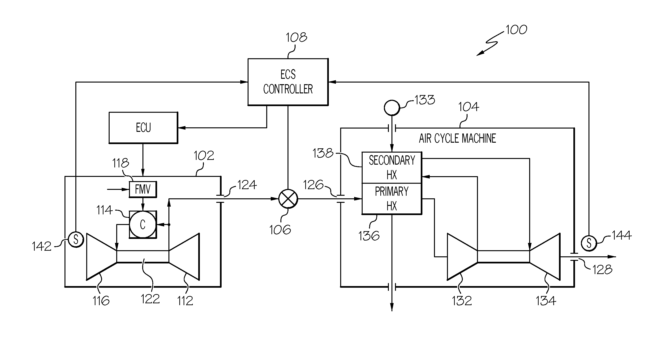
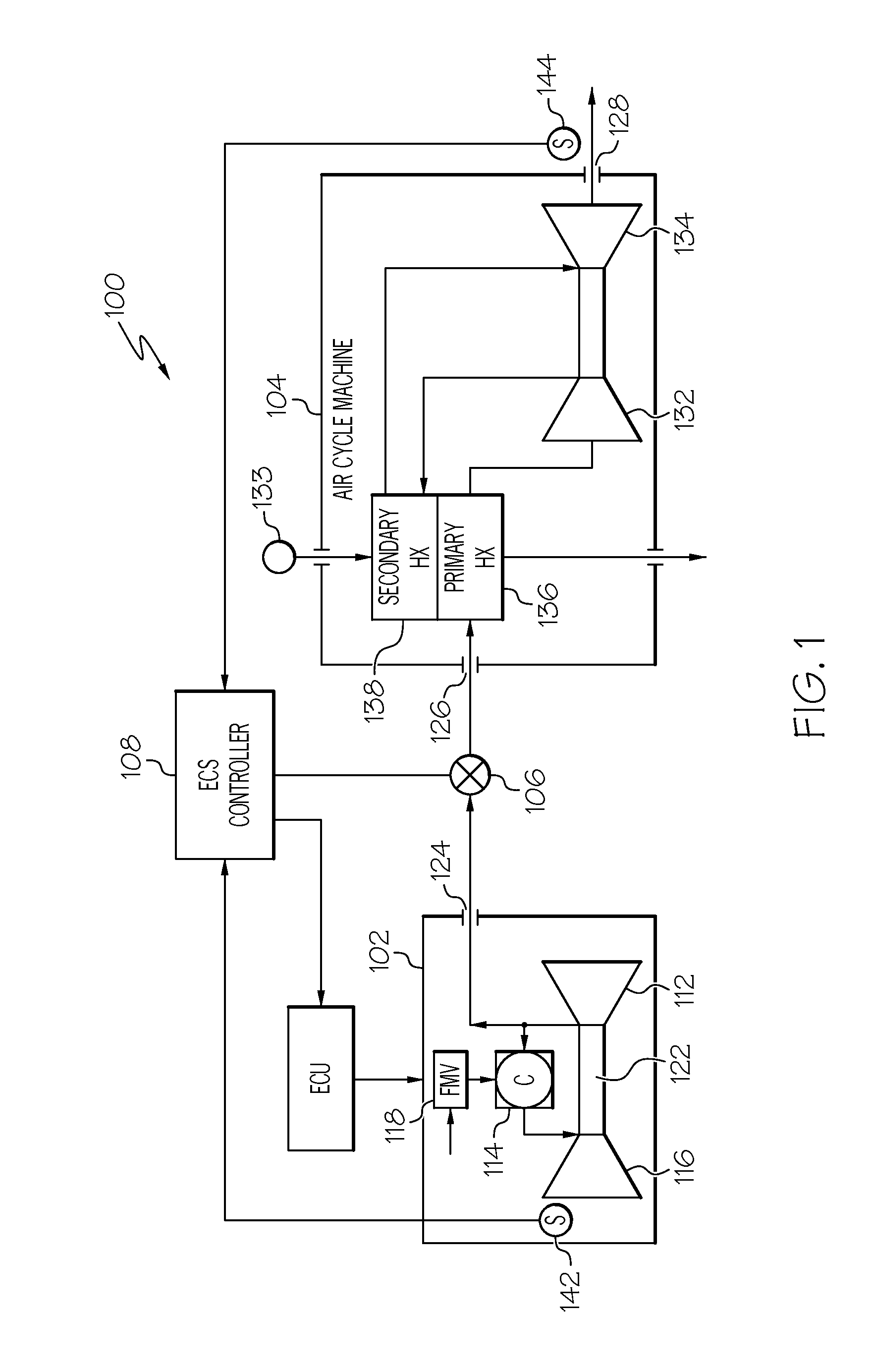
[0015]Referring to FIG. 1, a schematic representation of a portion of one embodiment of an aircraft environmental control system (E...


PUM


Abstract

A system and method for controlling bleed air flow into an air cycle machine that includes a bleed air inlet and a conditioned air outlet is provided. The system and method include discharging bleed air from an operating gas turbine engine, sensing exhaust gas temperature (EGT) of the gas turbine engine, sensing conditioned air temperature at the conditioned air outlet, and controlling bleed air flow into the air cycle machine based on the sensed EGT and on the sensed conditioned air temperature.

Description

TECHNICAL FIELD[0001]The present invention generally relates to aircraft environmental controls, and more particularly relates to an aircraft environmental control system (ECS) inlet flow control system and method that more closely matches ECS demand with bleed air supply flow capacity.BACKGROUND[0002]In many aircraft, main propulsion engines not only provide propulsion for the aircraft, but may also be used to drive various other rotating components such as, for example, generators, compressors, and pumps, to thereby supply electrical and / or pneumatic power. However, when an aircraft is on the ground, its main engines may not be operating. Moreover, in some instances the main propulsion engines may not be capable of supplying the power needed for propulsion as well as the power to drive these other rotating components. Thus, many aircraft include an auxiliary power unit (APU) to supplement the main propulsion engines in providing electrical power to electrical loads and / or bleed ai...

Claims


Application Information

Patent Timeline
IPC IPC(8): B64D41/00F02C9/18B64D13/08
CPCB64D41/00F02C9/18B64D13/08B64D13/06B64D2013/0611B64D2013/0618B64D2013/0648F02C6/08F02C7/141F02C7/32F05D2270/313Y02T50/50
Inventor SHEPARD, ERICWOLOWNIK, TODD
Owner HONEYWELL INT INC
Learn More