
Power tool battery pack

Active Publication Date: 2014-10-09
MAKITA CORP
View PDF6 Cites 34 Cited by
  • Summary
  • Abstract
  • Description
  • Claims
  • Application Information

AI Technical Summary

Benefits of technology

The power tool battery pack has a feature that prevents water from causing electrical connections between certain terminals. This is accomplished by using an insulating material that creates space between the terminals, even if water reaches them. This prevents unintended electrical connections from being made between the signal terminals, which can protect the battery and improve its performance.

Problems solved by technology

As such, the power tools and battery packs may get wet—from rain or other sources of water / moisture in the environment in which the power tool is used.
There is thus a risk that water may adversely come into contact with the signal terminals.
Such an unintended connection might be interpreted, erroneously, as the transmission and / or reception of information related to power tool or battery pack operation or control, and this might result in the improper operation of the power tool and / or battery pack.
In order to address this problem, it would be possible to protect signal terminals by coating them with, for example, a low temperature, low pressure type molding resin, sometimes called “hot melt molding” However, merely coating the signal terminals with such a low temperature, low pressure type molding resin has been criticized as being insufficient to protect the signal terminals
Therefore, even if water contacts the first terminal and / or second terminal, the terminals are spaced apart (isolated) by the slit and thus can not be electrically connected or shorted together by the water.

Method used


Image

  • Power tool battery pack
  • Power tool battery pack
  • Power tool battery pack

Examples


first embodiment

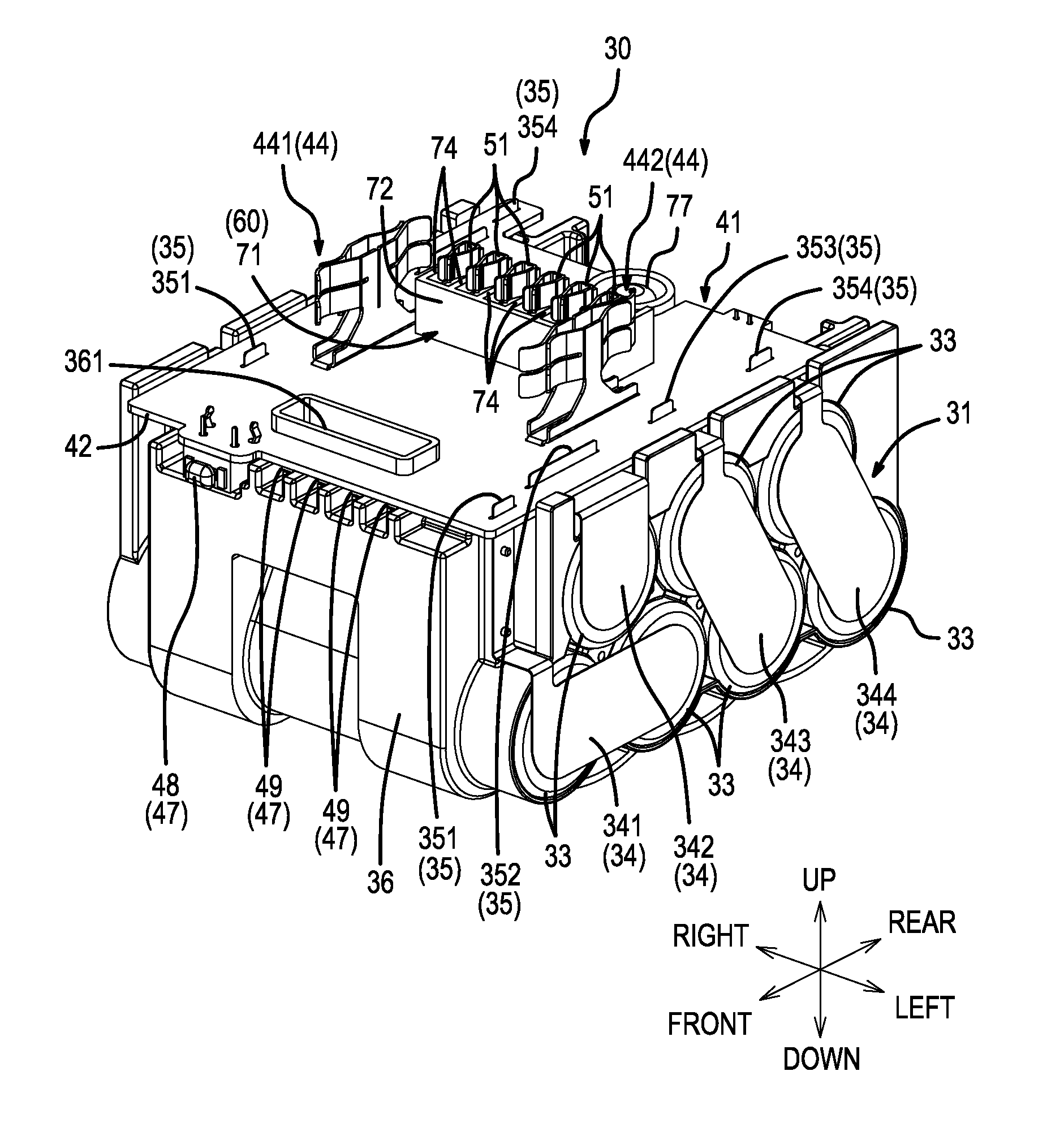
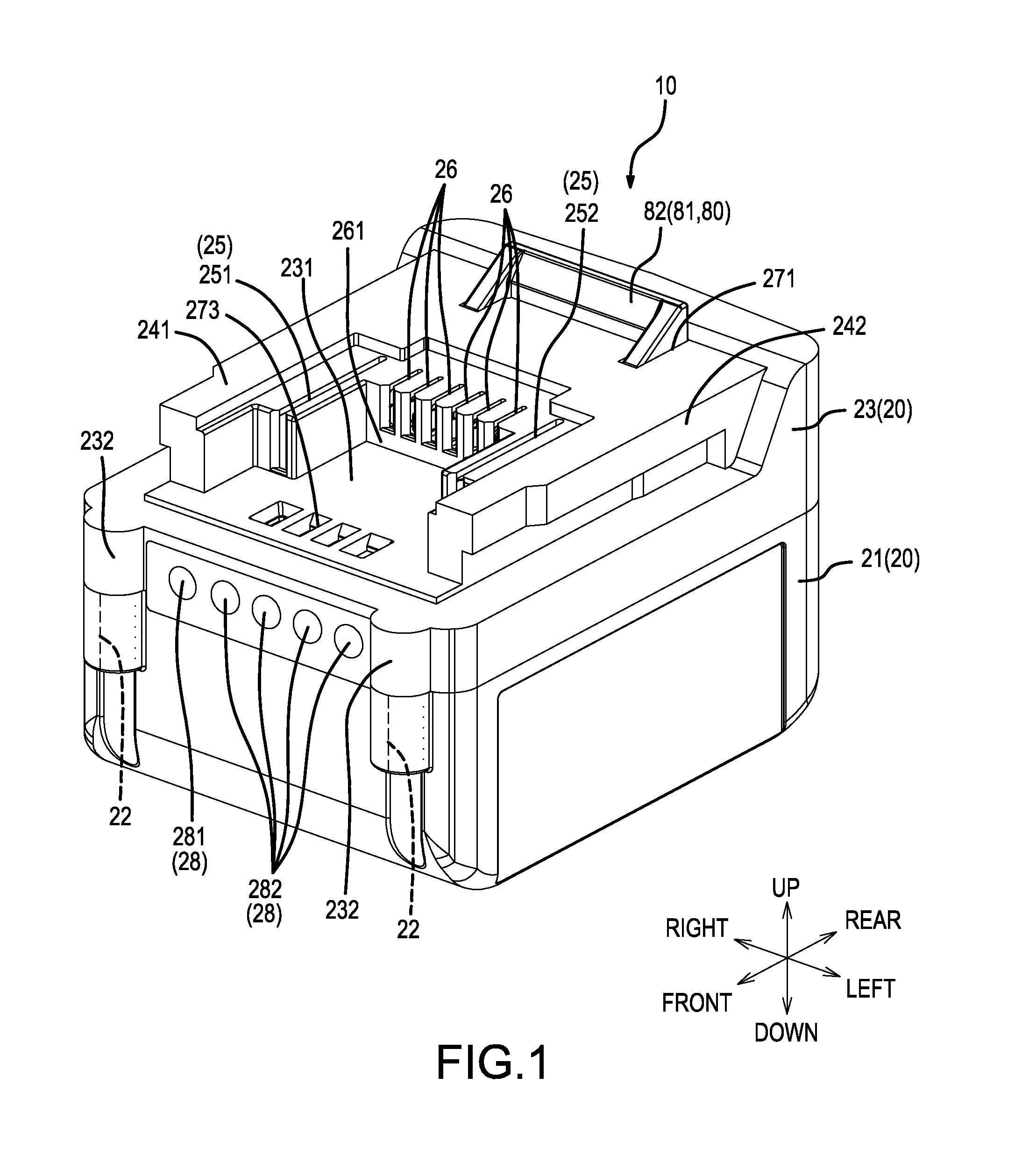
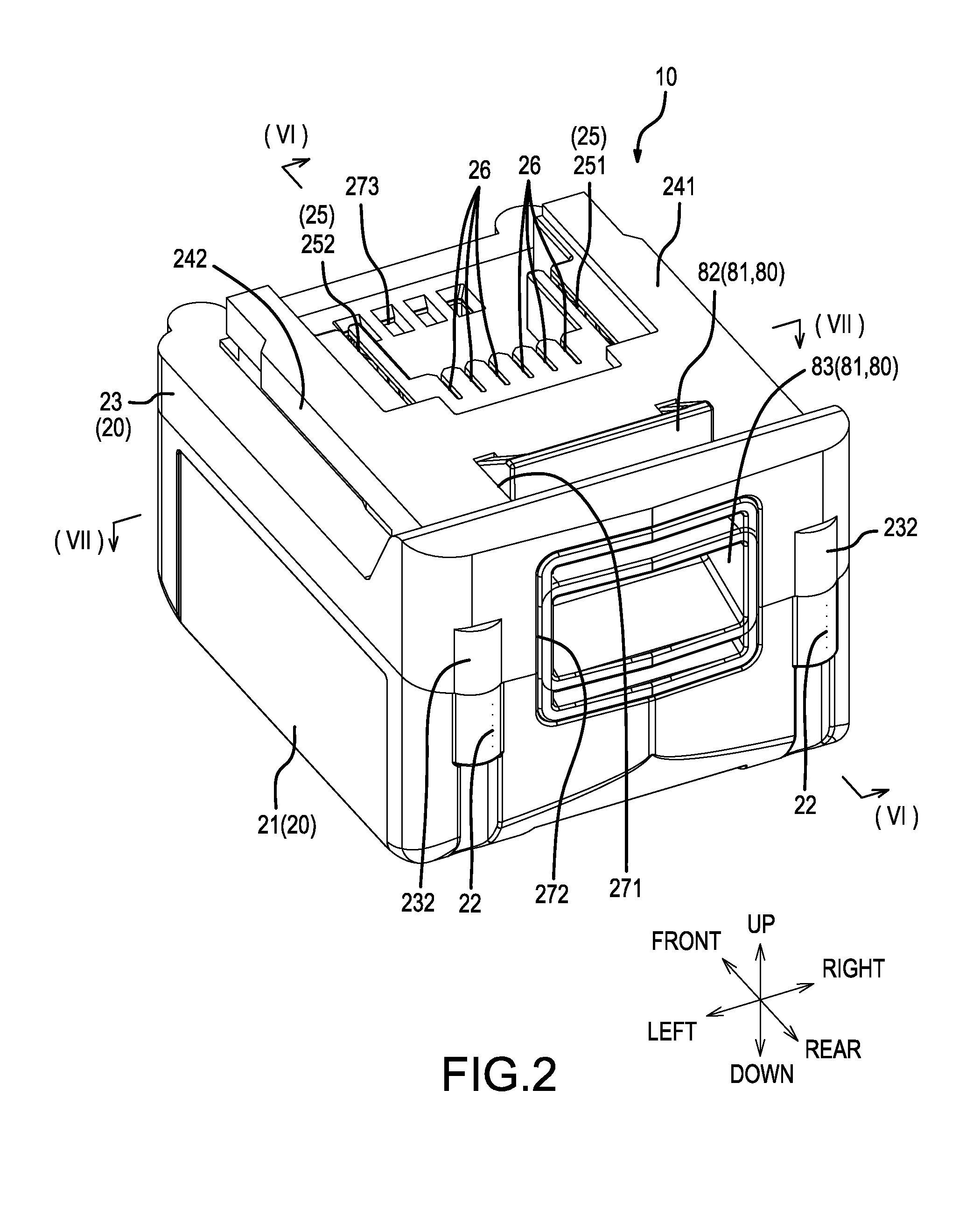
[0082]A first embodiment will be explained, referencing FIG. 1 through FIG. 10. Reference numeral 10 in the figures denotes a battery pack and corresponds to a representative power tool battery pack of the present disclosure. The battery pack 10 is a rechargeable battery that is configured to be attached to and detached from tool main bodies (i.e., mounting targets) by a sliding motion. The tool main bodies may be part of various power tools, for example, a power driver. The battery pack 10, when mounted to the tool main body, functions as a power supply of the power tool. If the amount of charge in the battery pack 10 runs low, then the battery pack 10 is detached from the tool main body and mounted to a specialized charger (i.e., a mounting target) for charging. When charging is complete, the battery pack 10 can be removed from the charger and reconnected to the same or to a different power tool.

[0083]The text below describes the battery pack 10 with respect to the front, rear, up...

second embodiment

[0124]A second embodiment of a power tool battery pack of the present disclosure is explained below, with reference to FIG. 12 through FIG. 22. Furthermore, the second embodiment is a modified example of the first embodiment, elements corresponding to those of the first embodiment are assigned the same reference numerals in FIGS. 12-22, and explanations of many of these elements are omitted. The following discussion is directed principally to the structures and members that differ from those in the first embodiment.

[0125]As shown in FIG. 12 and FIG. 13, similar to the battery pack according to the first embodiment, a battery pack 110 according to the present embodiment substantially comprises an outer packaging case 20 and the battery main body 30 (see, for example, FIG. 14), which is installed inside the outer packaging case 20. The outer packaging case 20 functions as a casing that, while forming an outer packaging of the battery pack 110, is internally equipped with the battery m...

third embodiment

[0137]Next, a battery pack 110A according to a third embodiment, which is a modified example of the battery pack 110 of the abovementioned second embodiment, will be explained, with reference to FIG. 23 through FIG. 30. Furthermore, except for the arrangement and configuration of the partition part 160, the battery pack 110A of the third embodiment is configured substantially the same as the battery pack 110 of the abovementioned second embodiment. The battery pack 110A of the third embodiment differs in the arrangement and configuration of the partition part 160 from the battery pack 110 of the abovementioned second embodiment. Consequently, in the explanation below, emphasis will be given to the arrangement and configuration of a partition part 160A in the battery pack 110A of the third embodiment. Elements of the battery pack 110A of the third embodiment that are configured identically to those in the battery pack 110 of the abovementioned second embodiment are assigned identical...


PUM


Abstract

A power tool battery pack includes a lower side case, an upper side case fixed to the lower side case, a battery cell in the lower side case and a circuit board connected to the battery cell. A plurality of electrical signal terminals are arranged in parallel on the circuit board, and the circuit board includes at least one slit between adjacent pairs of the plurality of signal terminals to make it difficult for any water that reaches the circuit board to electrically short two of the signal terminals together. Alternately or in addition, a wall structure may be provided between the terminals for reducing the likelihood that water reaching one of the signal terminals will be able to electrically connect two of the signal terminals.

Description

CROSS-REFERENCE[0001]This application claims priority to Japanese patent application nos. 2013-079594, 2013-079595 and 2013-079596, each filed on Apr. 5, 2013, the contents of each of which are fully incorporated herein by reference.TECHNICAL FIELD[0002]The present disclosure is directed to a power tool battery pack that can be used as a power supply of a power tool and that is attachable to and detachable from a main body of the power tool.BACKGROUND ART[0003]Power tools are known that have a battery pack, which serves as a power supply, mounted to a tool main body (e.g., refer to the page on which the BL1430 appears in the Makita General Catalog published April 2012). Such a power tool battery pack comprises a rechargeable battery that can be attached to and detached from the tool main body. That is, after the power tool battery pack is attached to the tool main body and used, the power tool battery pack is detached from the tool main body and charged by a specialized charger. Aft...

Claims


Application Information

Patent Timeline
IPC IPC(8): H01M2/10H01M50/296H01M50/50H01M50/569H01M50/572
CPCH01M2/1055H01M50/213H01M50/572H01M50/296H01M50/569H01M50/50H01M10/425H01M2220/30Y02E60/10
Inventor OGURA, HIRONORI
Owner MAKITA CORP
Learn More