
Waterproof structure of wire leading portion

A waterproof structure, electric wire technology, applied in the direction of circuits, vehicle parts, electrical components, etc., can solve the problems of poor operability, rubber cap movement, etc., and achieve the effect of reliable position, improved operability, and uncomplicated assembly work

Active Publication Date: 2015-01-21
YAZAKI CORP
View PDF7 Cites 0 Cited by
  • Summary
  • Abstract
  • Description
  • Claims
  • Application Information

AI Technical Summary

Problems solved by technology

The problem with this waterproof structure is that if the internal pressure of the case changes, the rubber cap may move
Therefore, operability deteriorates

Method used


Image

  • Waterproof structure of wire leading portion
  • Waterproof structure of wire leading portion
  • Waterproof structure of wire leading portion

Examples


Embodiment Construction

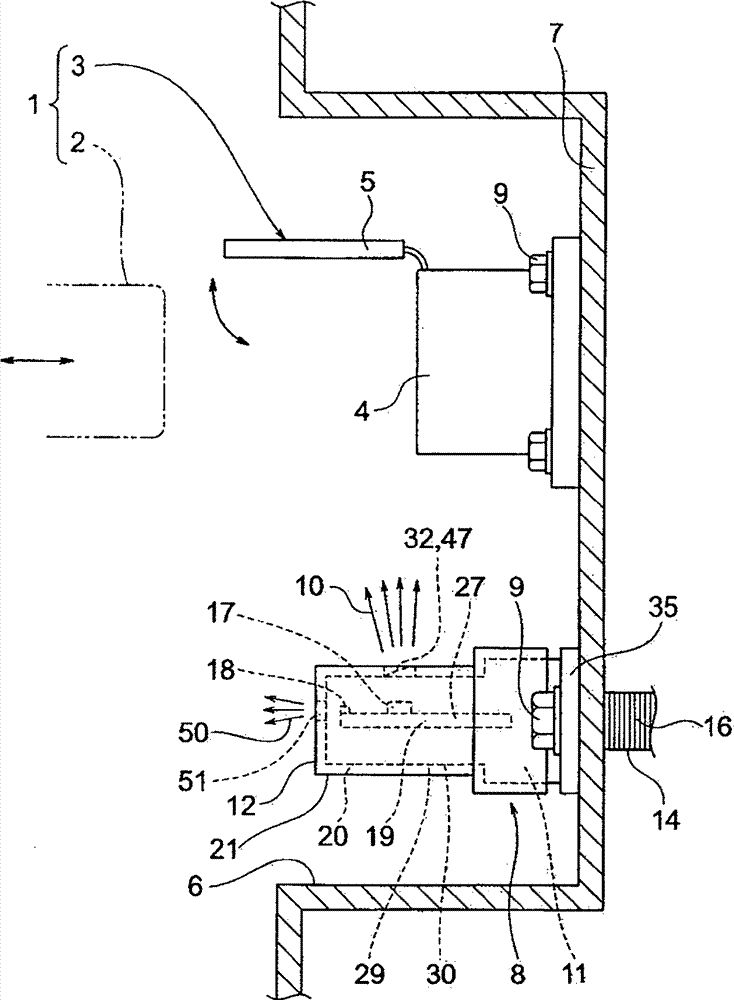
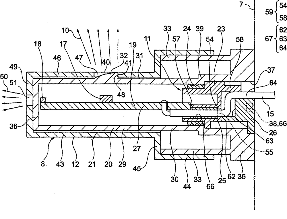
[0029] A waterproof structure is adopted in which the outer surface of the seal holder and the inner surface of the housing are sealed by the seal with respect to the wire lead-out portion, and the rubber cap accommodation chamber of the seal holder and the wire pass through Rubber cap seal. Furthermore, a waterproof structure is adopted in which the rubber cap is held by the cross section of the circuit board and the inner surface of the rubber cap detachment prevention wall. Furthermore, an electric wire maintaining structure is employed in which the electric wire drawn out from the outer surface of the rubber cap drop-off preventing wall is maintained in a bent state by the seal holder and the respective bend maintaining portions of the holder.

[0030] Hereinafter, embodiments will be described in detail with reference to the accompanying drawings. figure 1 is a view showing the arrangement of the lighting unit and the charger connector employing the waterproof structure ...


PUM


Abstract

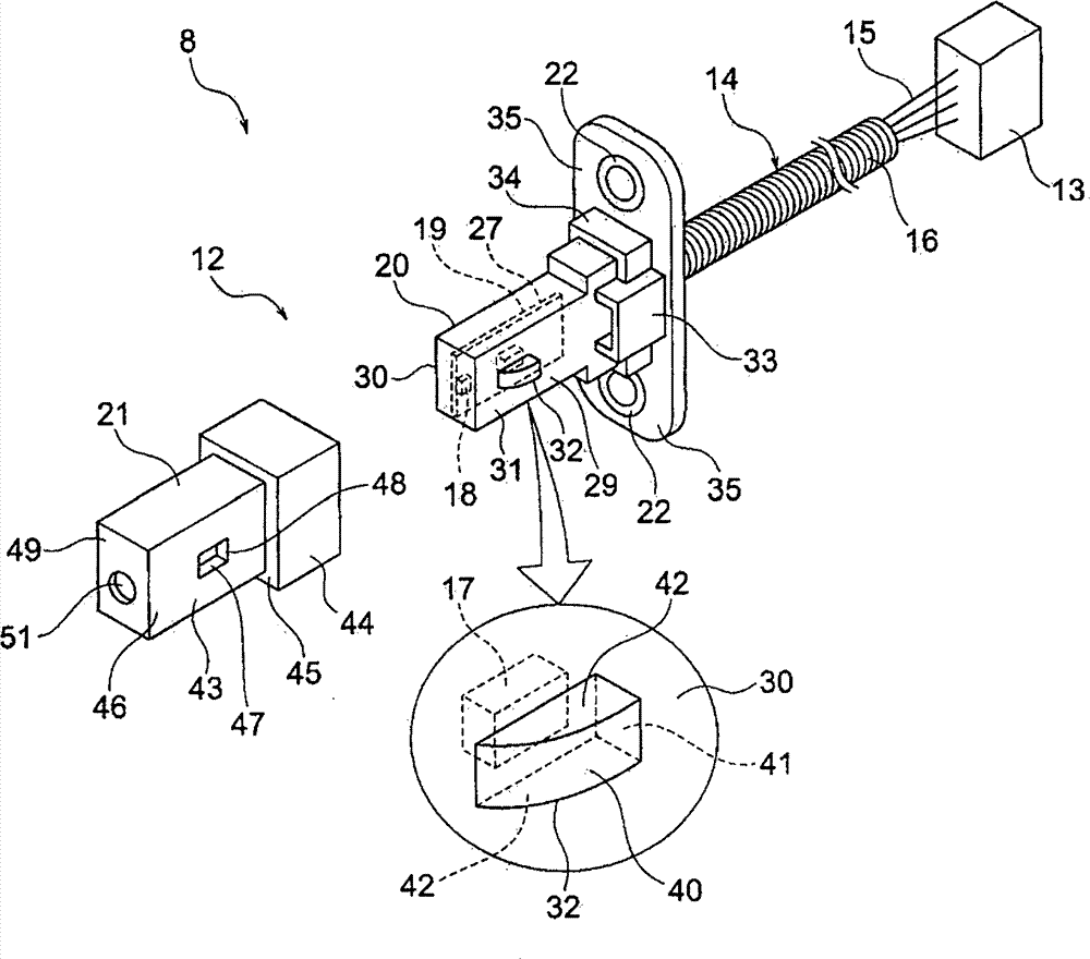
There is provided a waterproof structure of a wire leading portion. A rubber cap is assembled with wire connected to a circuit board. A housing accommodates the circuit board. A packing holder is accommodated next to the circuit board through an opening of the housing. A packing is assembled on an outer periphery of the packing holder to be in close contact with an inner surface of the housing. The packing holder includes: a rubber cap secession prevention wall formed in a direction that crosses an accommodation direction; a wire insertion hole formed to penetrate the wall; and a rubber cap accommodation chamber communicating with the wire insertion hole and continuing to an inner surface of the wall. The inner surface of the wall and a cross-section of the circuit board are formed to hold the rubber cap that is accommodated in the rubber cap accommodation chamber.

Description

[0001] The entire disclosure of Japanese Patent Application No. 2011-052530 filed on Mar. 10, 2011 including specification, drawings and claims is incorporated herein by reference in its entirety. technical field [0002] The present invention relates to a waterproof structure employable in an electric wire lead-out portion for leading out electric wires from a housing. Background technique [0003] In an electric vehicle or a hybrid vehicle, battery charging is performed using a charger connector composed of a power feeding side connector and a power receiving side connector (vehicle side inlet). [0004] Patent Document 1 discloses technology related to a charger connector. According to this disclosed technology, the power receiving side connector is installed in the power receiving side accommodation room in the vehicle. In addition, a lamp is also installed in the power receiving side accommodation chamber. The lamp is a component constituting the lighting unit, and is...

Claims


Application Information

Patent Timeline
Patent Type & Authority Patents(China)
IPC IPC(8): H01R13/52H01R13/717B60Q3/06F21Y101/00
CPCF21S48/33B60Q3/06B60Q3/30F21S45/50
Inventor 泽柳昌広
Owner YAZAKI CORP
Learn More