
Method and apparatus for joining together multiple functional layers of a flexible display

a flexible display and functional layer technology, applied in the field of joining multiple layers of a flexible display, can solve the problems of limited flexibility of such flexible displays, and achieve the effects of improving flexibility, enhancing display flexibility, and improving flexibility

Active Publication Date: 2014-10-02
LYTEN INC
View PDF1 Cites 143 Cited by
  • Summary
  • Abstract
  • Description
  • Claims
  • Application Information

AI Technical Summary

Benefits of technology

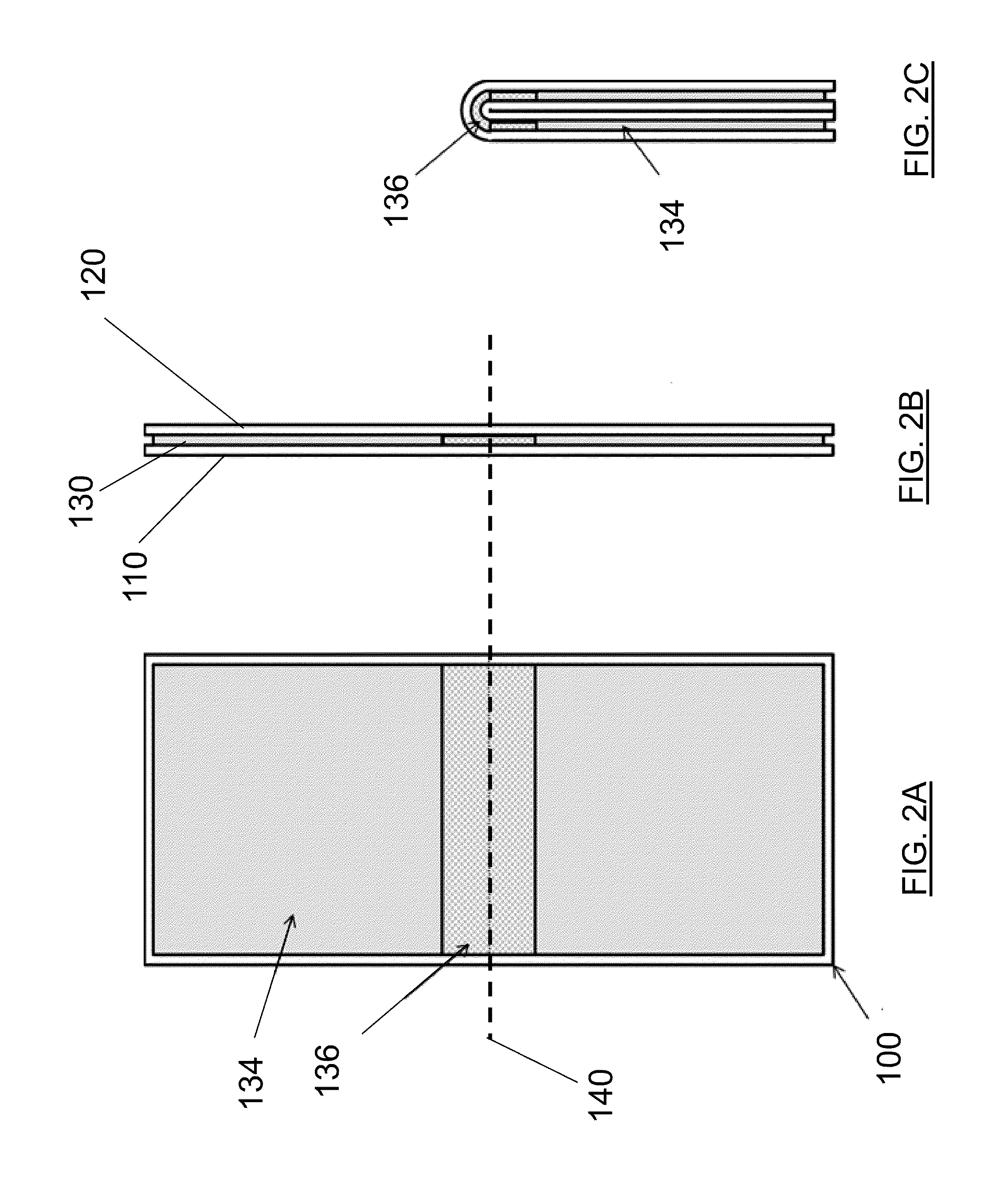
The patent text describes a method and apparatus for improving the flexibility of flexible displays by using materials that enhance the flexibility of the display. This is particularly important at areas where the greatest degree of flexing may occur. The method includes depositing a layer of optically clear adhesive (OCA) on a first substrate and laminating a second substrate to the OCA opposite the first substrate. The OCA has a first region with a first elastic modulus and a second region with a second elastic modulus, which is different than the first elastic modulus. The second elastic modulus is lower than the first elastic modulus, and the second region of the OCA defines a region of the display stack with greater flexibility than a region defined by the first region of the OCA. The OCA may be cross-linked to a first degree in the first region and cross-linked to a second degree that is different from the first degree in the second region. The first region of the OCA may be cured in response to exposure to ultraviolet radiation. The technical effect of this invention is to provide improved flexibility and durability of flexible displays.

Problems solved by technology

However, the flexibility of such flexible displays is limited, at least in part, by the materials used to create the displays and the movement between the various layers of the display during flexing.

Method used


Image

  • Method and apparatus for joining together multiple functional layers of a flexible display
  • Method and apparatus for joining together multiple functional layers of a flexible display
  • Method and apparatus for joining together multiple functional layers of a flexible display

Examples


Embodiment Construction

[0017]Some embodiments of the present invention will now be described more fully hereinafter with reference to the accompanying drawings, in which some, but not all embodiments of the invention are shown. Indeed, various embodiments of the invention may be embodied in many different forms and should not be construed as limited to the embodiments set forth herein; rather, these embodiments are provided so that this disclosure will satisfy applicable legal requirements. Like reference numerals refer to like elements throughout. As used herein, the terms “data,”“content,”“information” and similar terms may be used interchangeably to refer to data capable of being transmitted, received and / or stored in accordance with some embodiments of the present invention. Thus, use of any such terms should not be taken to limit the spirit and scope of embodiments of the present invention.

[0018]Additionally, as used herein, the term ‘circuitry’ refers to (a) hardware-only circuit implementations (e....


PUM

PropertyMeasurementUnit
Flexibilityaaaaaaaaaa
Heataaaaaaaaaa
Elastic modulusaaaaaaaaaa

Abstract

The present invention may relate to provision of a mechanism to join together the various substrate layers of a flexible display with optically clear adhesives that permit improved flexibility of the substrate layer stack and may also optically guide images to locations on a display surface that are not aligned with the display layer of a substrate layer stack. Embodiments of the present invention may provide for an improved user interface which may include enhanced flexibility and enhanced optical characteristics.

Description

TECHNOLOGICAL FIELD[0001]Some example embodiments of the present invention relate generally to the joining of multiple layers of a display of a device with an optically clear adhesive, and more particularly, to the joining of multiple layers of a flexible display with an optically clear adhesive that affords greater flexibility at specific locations of the display.BACKGROUND[0002]In recent years, considerable progress has been made toward the development of thin and flexible displays. For example, it is known to have a display device assembly including a flexible display device being rollable around an axis. A range of flexible electronic devices based on these technologies including full color, high-resolution flexible organic light emitting diode, OLED, displays with a thickness of less than one millimeter are being introduced to the market. The goal of such efforts is to provide displays with superior handling, contrast, and flexibility.[0003]While conventional displays have been...

Claims


Application Information

Patent Timeline
IPC IPC(8): C09J7/02C09J7/10
CPCC09J7/02B32B7/12C09J5/00C09J7/00C09J2201/40C09J2203/318C09J2205/31Y10T428/24851Y10T428/31504G02F1/133305G02F2202/28C09J7/10Y02E10/549C09J2301/21C09J2301/416Y02P70/50B32B25/16B32B2457/208B32B27/36B32B27/365B32B27/302B32B2250/02B32B2274/00B32B25/20B32B2457/206B32B27/40B32B15/09B32B25/12B32B27/306B32B27/281B32B15/085B32B27/308B32B27/32B32B2457/202B32B15/082B32B15/06B32B15/095B32B27/08B32B27/283B32B17/10H10K77/111
Inventor BOWER, CHRISALLEN, MARKCOTTON, DARRYLANDREW, PIERS
Owner LYTEN INC
Learn More