
X-Ray Fluorescence Spectrometer

a fluorescence spectrometer and x-ray technology, applied in the field of x-ray fluorescence spectrometers, can solve the problems of failure, poor workability, sensitivity lowering, etc., and achieve the effects of improving sensitivity and throughput, stable measurement, and high-sensitivity analysis

Active Publication Date: 2014-10-02
HITACHI HIGH TECH SCI CORP
View PDF29 Cites 0 Cited by
  • Summary
  • Abstract
  • Description
  • Claims
  • Application Information

AI Technical Summary

Benefits of technology

The invention provides an X-ray fluorescence spectrometer that can prevent samples or other materials from attaching to the detector and improve sensitivity and throughput of analysis. The spectrometer uses a gas blowing mechanism to prevent attachment, without using a Mylar film that may absorb characteristic X-rays and lower sensitivity. The gas blowing mechanism can also prevent the sample from scattering and attaching to the detector. The gas used for blowing can be He, which has lower absorption of characteristic X-rays than air, resulting in higher sensitivity for analyzing light elements. The detector may also have a collimator section to set the opening degree of the X-ray incident window and the gas blowing mechanism may include an internal gas flow passage with multiple blow out holes for effectively preventing attachment. The advantages of the invention include improved sensitivity, throughput, and prevention of sample attachment to the detector.

Problems solved by technology

In the above-described related-art X-ray fluorescence spectrometer, since a Mylar film is used, some of X-rays are absorbed by the Mylar film, so that there may cause a disadvantage that the sensitivity is lowered.
In the case where a sample or the like is attached to the Mylar film and the Mylar film is contaminated, it is necessary to replace the Mylar film with a new one, and there is a further disadvantage that the workability is poor.
Moreover, there may be a possibility that fine powder or the like produced during replacement of the Mylar film may attach to the beryllium windows of the detector and the X-ray bulb, and a failure may be caused.

Method used


Image

  • X-Ray Fluorescence Spectrometer
  • X-Ray Fluorescence Spectrometer
  • X-Ray Fluorescence Spectrometer

Examples


Embodiment Construction

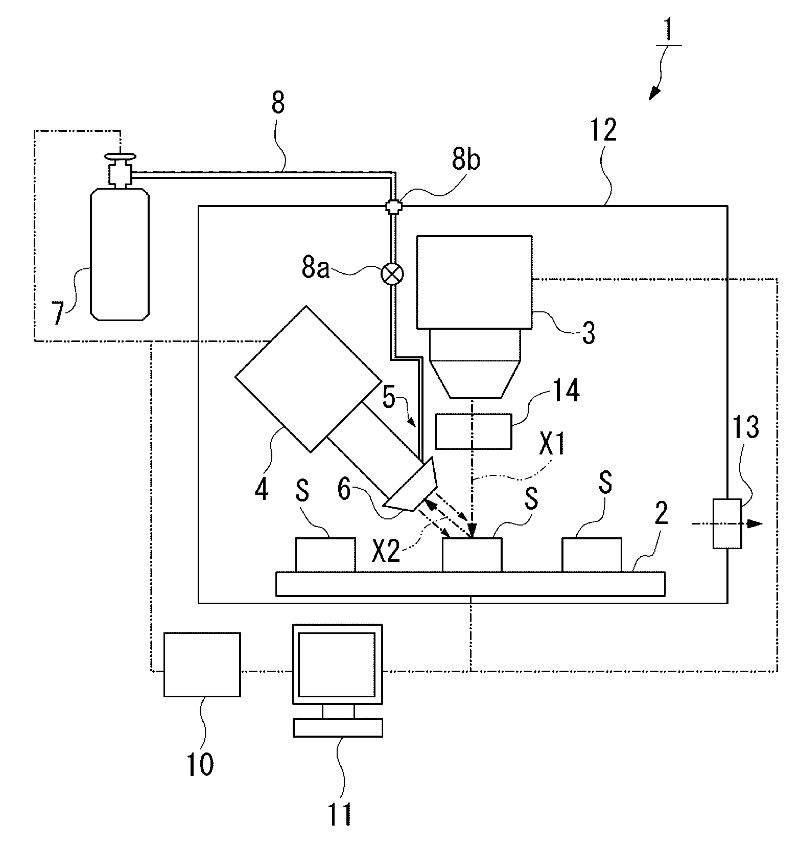
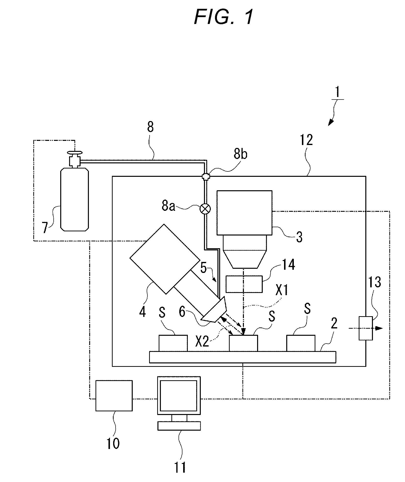
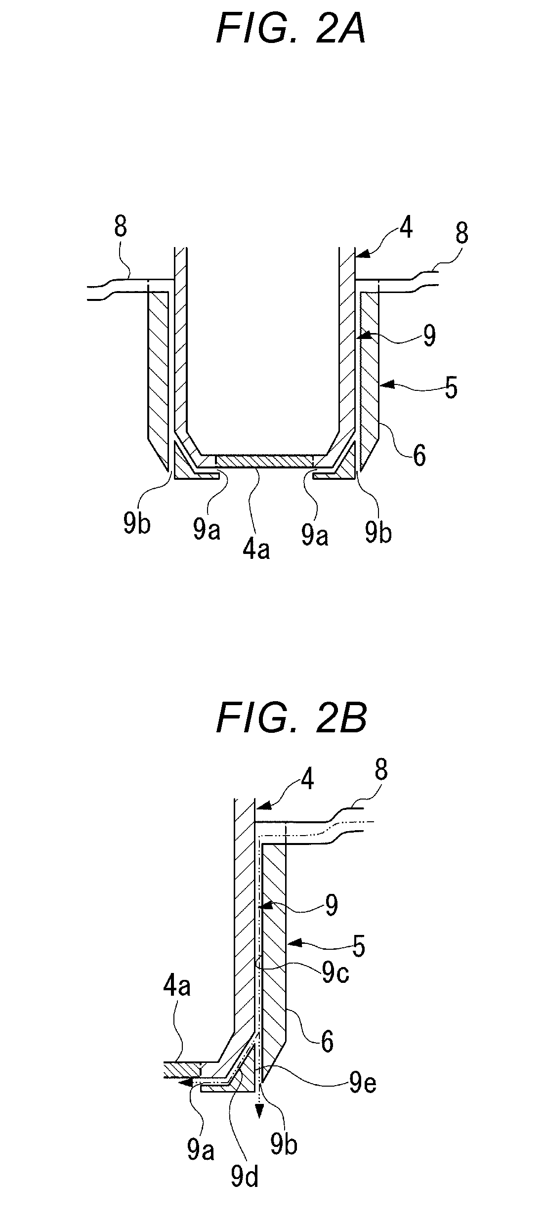
[0024]Hereinafter, an illustrative embodiment of the X-ray fluorescence spectrometer of the invention will be described with reference to FIGS. 1, 2A and 2B.

[0025]As shown in FIGS. 1, 2A and 2B, an X-ray fluorescence spectrometer 1 of the illustrative embodiment includes: a sample stage 2 configured to place a sample S thereon; an X-ray source 3 configured to irradiate the sample S with primary X-rays X1; a detector 4, which is configured to detect fluorescent X-rays X2 produced from the sample S irradiated with the primary X-rays X1, and which has an X-ray incident window 4a formed by a window material through which the fluorescent X-rays X2 can be transmitted; and a gas blowing mechanism 5 configured to blow a gas to the outer surface of the X-ray incident window 4a. The X-ray source 3, the sample stage 2, and parts of the detector 4 and the gas blowing mechanism 5 are accommodated in a housing 12 of the X-ray fluorescence spectrometer 1.

[0026]The X-ray fluorescence spectrometer 1...


PUM

PropertyMeasurementUnit
gas flow rateaaaaaaaaaa
degree of freedomaaaaaaaaaa
fluorescenceaaaaaaaaaa

Abstract

An X-ray fluorescence spectrometer includes: a sample stage configured to place a sample thereon; an X-ray source configured to irradiate the sample with primary X-rays; a detector, which is configured to detect fluorescent X-rays produced from the sample irradiated with the primary X-rays, and which includes an X-ray incident window formed by a window material through which fluorescent X-rays is transmittable; and a gas blowing mechanism configured to blow a gas to at least one of an outer surface of the X-ray incident window and the sample stage.

Description

[0001]This application claims priority from Japanese Patent Application No. 2013-068420 filed on Mar. 28, 2013, the entire subject-matter of which is incorporated herein by reference.BACKGROUND[0002]1. Technical Field[0003]The disclosure relates to an X-ray fluorescence spectrometer which is configured to perform detection of a hazardous substance or the like, and which is used for, for example, screening products, or measuring the film thickness of plating or the like.[0004]2. Description of the Related Art[0005]In the X-ray fluorescence spectroscopy, a sample is irradiated with X-rays emitted from an X-ray source, and fluorescence X-rays which are characteristic X-rays released from the sample are detected by an X-ray detector. A spectrum is obtained from the energy of the detected X-rays, and the sample is qualitatively or quantitatively analyzed, or the film thickness is measured. In the X-ray fluorescence spectroscopy, a sample can be rapidly analyzed in a non-destructive manne...

Claims


Application Information

Patent Timeline
Patent Type & Authority Applications(United States)
IPC IPC(8): G01N23/223
CPCG01N23/223G01N2223/076
Inventor NOHARA, HIROAKIMATOBA, YOSHIKISAKAI, NORIAKITAKEUCHI, TOSHITADA
Owner HITACHI HIGH TECH SCI CORP
Learn More