
Optical Spectrometer And Downhole Spectrometry Method

a technology of optical spectrometer and downhole spectrometry, which is applied in the direction of optical radiation measurement, borehole/well accessories, instruments, etc., can solve the problems of poor spectral resolution and inability to accurately analyze the spectrum with high wavelength resolution, and achieves improved reliability and serviceability, simple, robust, and compact

Active Publication Date: 2014-10-02
SCHLUMBERGER TECH CORP
View PDF13 Cites 5 Cited by
  • Summary
  • Abstract
  • Description
  • Claims
  • Application Information

AI Technical Summary

Benefits of technology

The disclosed patent describes an optical spectrometer and spectroscopy method that can recover the continuous transmittance spectrum of a fluid sample. This allows for a more complete investigation of the sample. Additionally, the spectrometer is designed to be compact, simple, and cost-effective, with a single measurement detector that improves reliability and serviceability. The technical effects include improved analytical capabilities and practicality for various industrial applications.

Problems solved by technology

Since downhole space constraints provide an upper limit on the number of bandpass filters that may be utilized, spectral resolution tends to be poor.
As such, precise spectrum analysis with high wavelength resolution tends not to be possible with a conventional type of downhole spectrometer.

Method used


Image

  • Optical Spectrometer And Downhole Spectrometry Method
  • Optical Spectrometer And Downhole Spectrometry Method
  • Optical Spectrometer And Downhole Spectrometry Method

Examples


Embodiment Construction

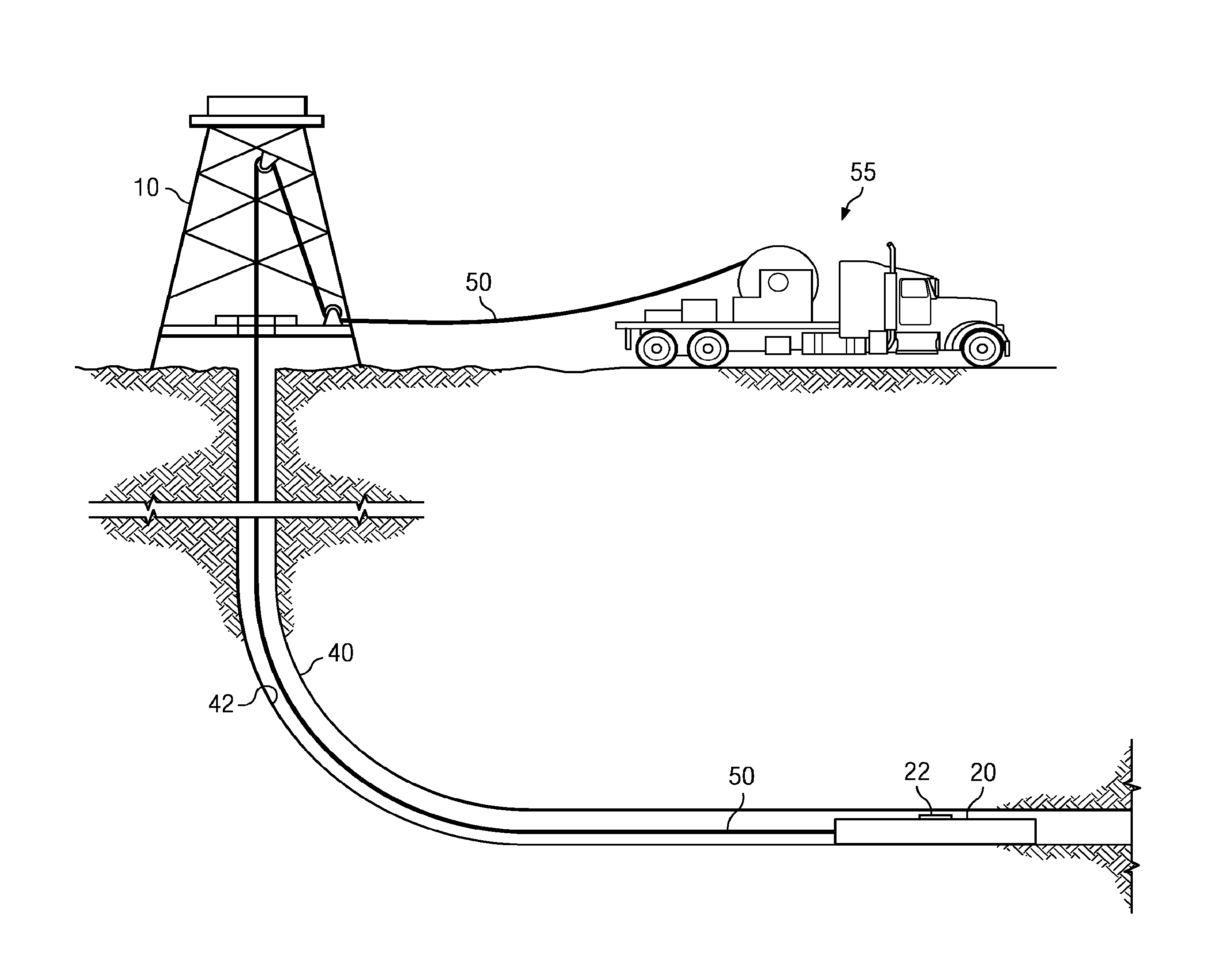
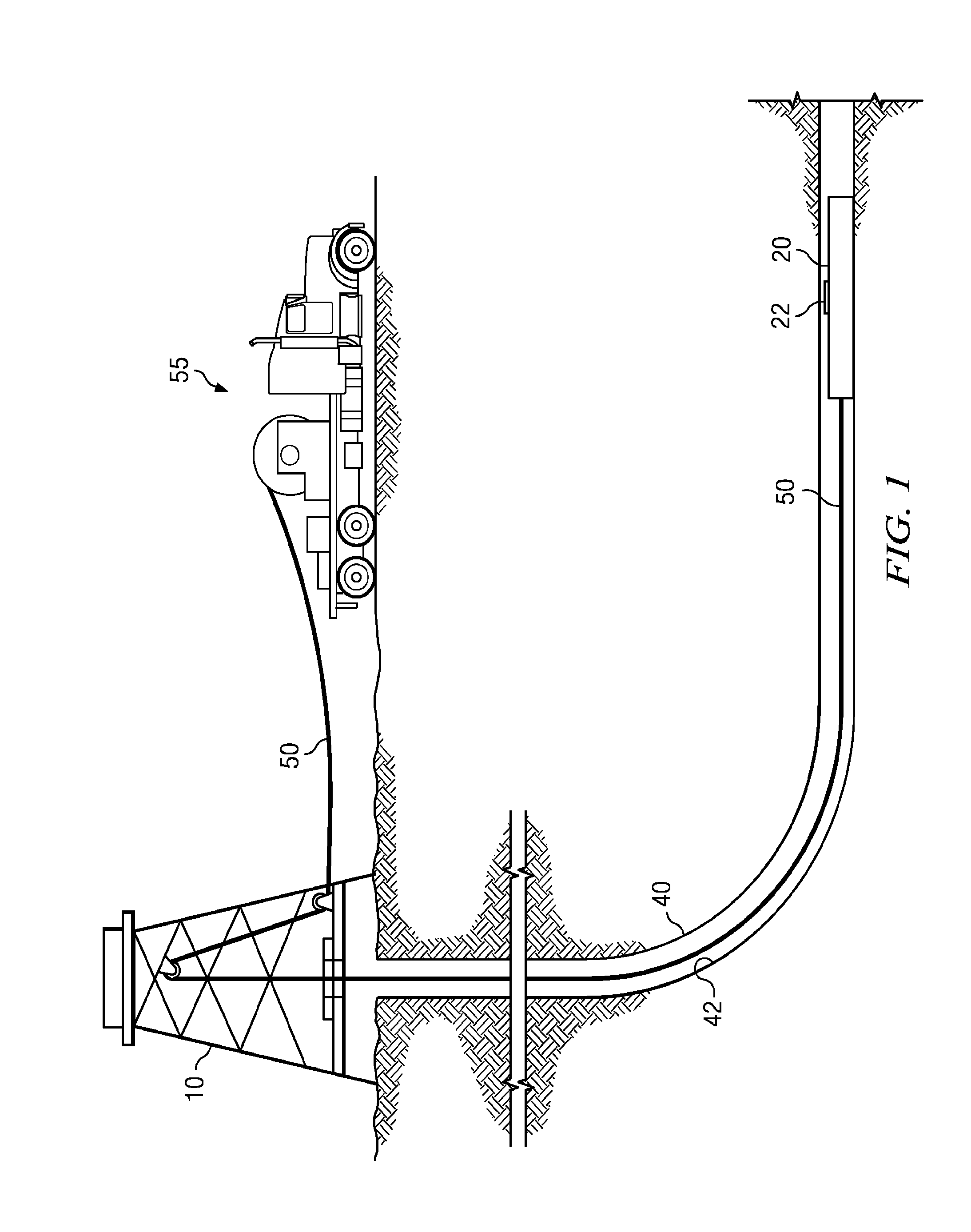
[0018]FIG. 1 depicts a drilling rig 10 suitable for employing certain downhole tool embodiments disclosed herein. In the depiction, a rig 10 is positioned over (or in the vicinity of) a subterranean oil or gas formation (not shown). The rig may include, for example, a derrick and a hoisting apparatus for lowering and raising various components into and out of the wellbore 40. A downhole wireline sampling tool 20 is deployed in the wellbore 40. The sampling tool may be connected to the surface, for example, via a wireline cable 50 which is in turn coupled to a wireline truck 55.

[0019]During a wireline operation, sampling tool 20 may be lowered into the wellbore 40. In a highly deviated borehole, the sampling tool 20 may alternatively or additionally be driven or drawn into the borehole using, for example, a downhole tractor or other conveyance means. The disclosed embodiments are not limited in this regard. Sampling tool 20 may also be conveyed into the borehole 40 using coiled tubin...


PUM


Abstract

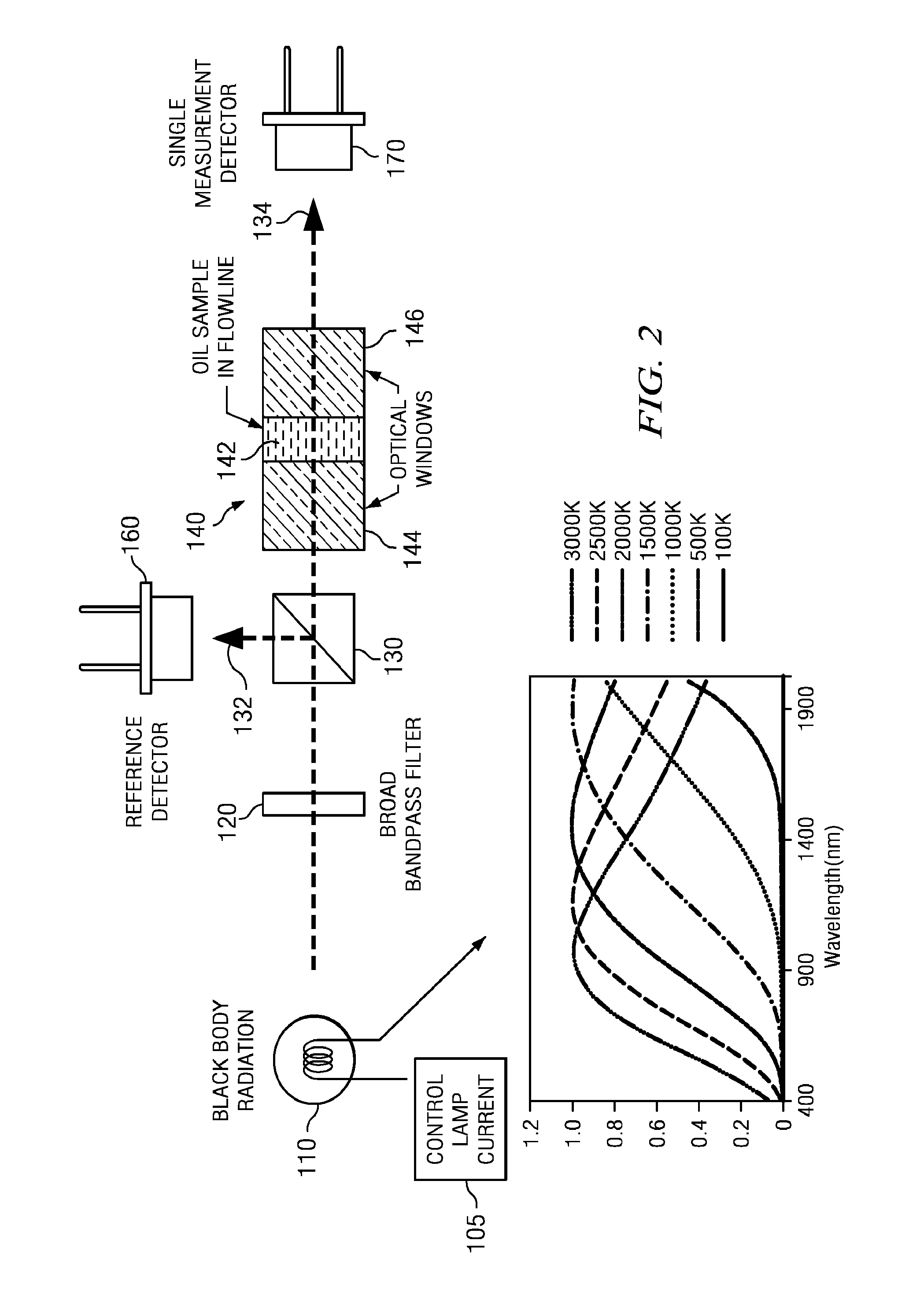
An optical spectrometer includes a near black body light source, a reference detector in a first optical path and a single measurement detector in a second optical path. A sample cell including a fluid flow line may be positioned in the second optical path upstream of the measurement detector. Optical energy ma be emitted at a plurality of filament temperatures and first and second sets of optical intensities measured at the reference and measurement detectors. The first and second sets of optical intensities may be processed to compute a substantially continuous transmittance spectrum of a fluid sample in the fluid flow line by inverting the acquired optical intensity measurements.

Description

FIELD OF THE INVENTION[0001]Disclosed embodiments relate generally to an apparatus and method for acquiring optical spectral data for downhole fluid analysis. More particularly the disclosed embodiments related to an apparatus and method employing a reference detector and a single measurement detector.BACKGROUND INFORMATION[0002]In order to successfully exploit subterranean hydrocarbon reserves, information about the subsurface formations and formation fluids intercepted by a wellbore is generally required. This information may be obtained via sampling and analyzing formation fluids during various drilling and completion operations. The fluid may be collected and analyzed, for example, to ascertain the petrophysical, mineralogical, and fluid properties of a hydrocarbon containing fluid reservoir. The analysis may be in turn utilized to evaluate the economic viability of the reservoir.[0003]Subterranean reservoirs commonly include a complex mixture of fluids including oil, gas, and w...

Claims


Application Information

Patent Timeline
IPC IPC(8): G01N21/25E21B49/08G01V8/12
CPCG01N21/255E21B49/088G01V8/12E21B49/08
Inventor INDO, KENTAROHSU, KAIPOP, JULIAN
Owner SCHLUMBERGER TECH CORP
Learn More