LED Backlight Driving Circuit, Backlight Module, and Liquid Crystal Display Device
a backlight driving circuit and backlight module technology, applied in the direction of instruments, discharge tubes/lamp details, optics, etc., can solve the problem of reducing working efficiency and other problems
- Summary
- Abstract
- Description
- Claims
- Application Information
AI Technical Summary
Benefits of technology
Problems solved by technology
Method used
Image
Examples
first embodiment
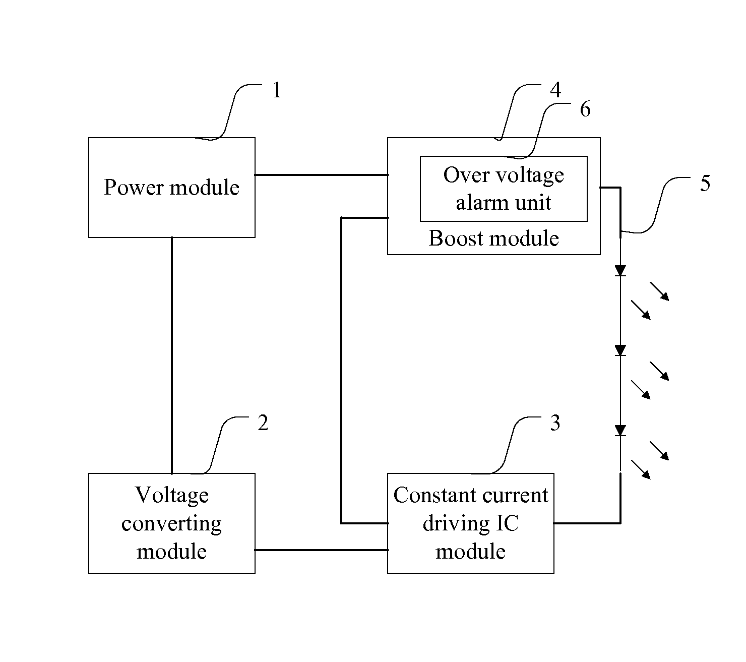
[0058]Referring to FIG. 2, it is a schematic structural diagram of the LED backlight driving circuit according to the present invention.
[0059]The LED backlight driving circuit according to the present invention comprises:[0060]a power module 1, a voltage converting module 2, a constant current driving IC module 3, a boost module 4;[0061]the output terminal of the power module 1 is connected with the power source of the constant current driving IC module 3 through the voltage converting module 2;[0062]the output terminal of the power module 1 is connected with the positive electrode of the LED strings 5 through the boost module 4;[0063]the boost module 4 is provided with an over voltage alarm unit 6 used to warn that the voltage of the positive electrode of the LED strings 5 is high. Wherein, when the LED driver circuit is working, the over voltage alarm unit 6 lighting indicates that the positive electrode voltage of the LED strings is under high voltage. At this time, the operator ...
second embodiment
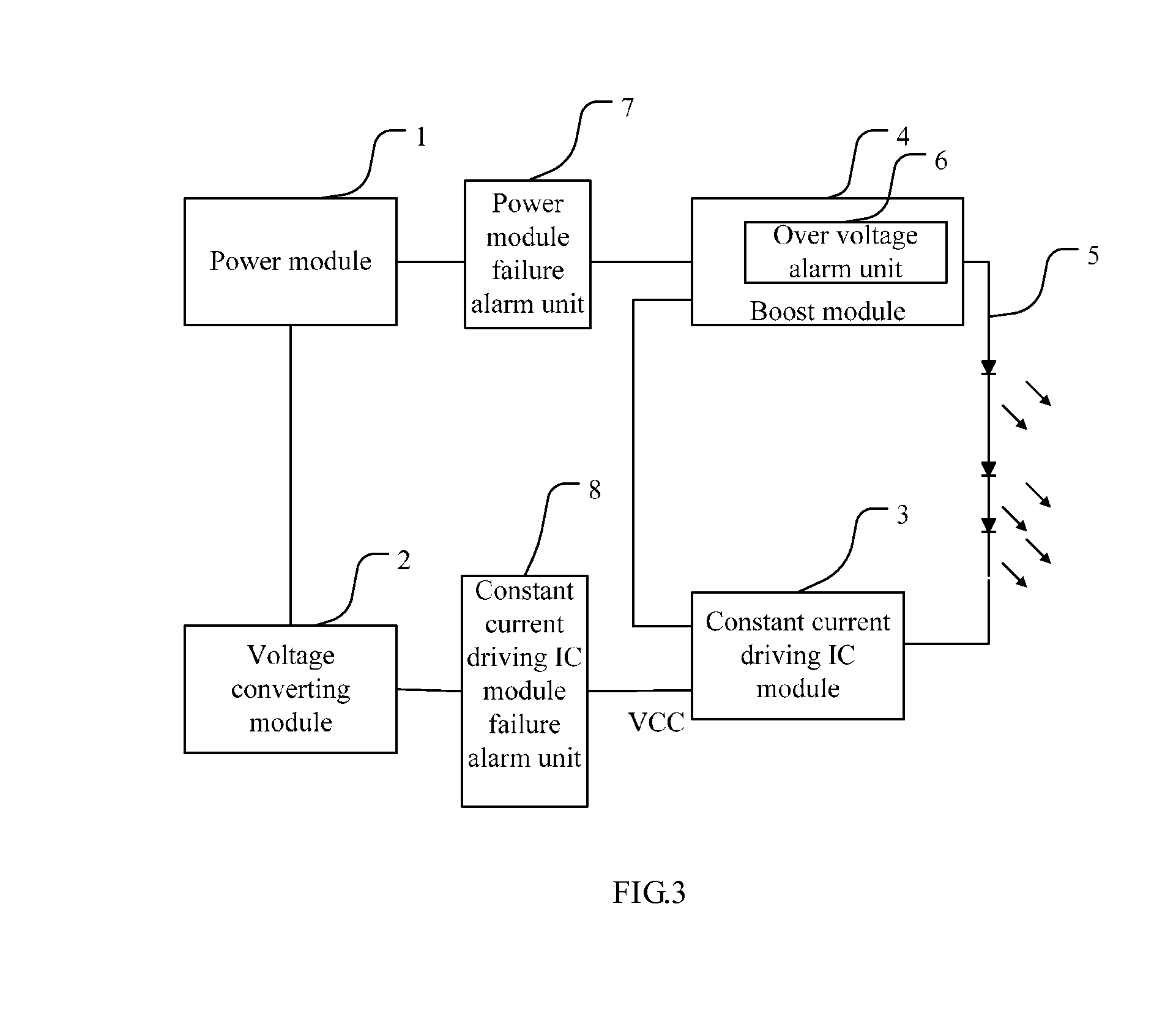
[0065]Referring to FIG. 3, it is a schematic structural diagram of the LED backlight driving circuit according to the present invention.
[0066]Except each module and component in the first embodiment, the LED backlight driving circuit according to the second embodiment further comprises:[0067]a power module failure alarm unit 7, which is used to indicate whether the power module 1 fails or not;[0068]a constant current driving IC module failure alarm unit 8, which is used to indicate whether the constant current driving IC module 3 fails or not.
[0069]Specifically, when the power module 1 of the LED backlight driving circuit is working normally, the power module failure alarm unit 7 lights up; when the power module failure alarm unit 7 lights off, it indicates the power module is failed.
[0070]When the constant current driving IC module 3 of the LED backlight driving circuit is working normally, the constant current driving IC module failure alarm unit 8 lights up; when the constant cur...
third embodiment
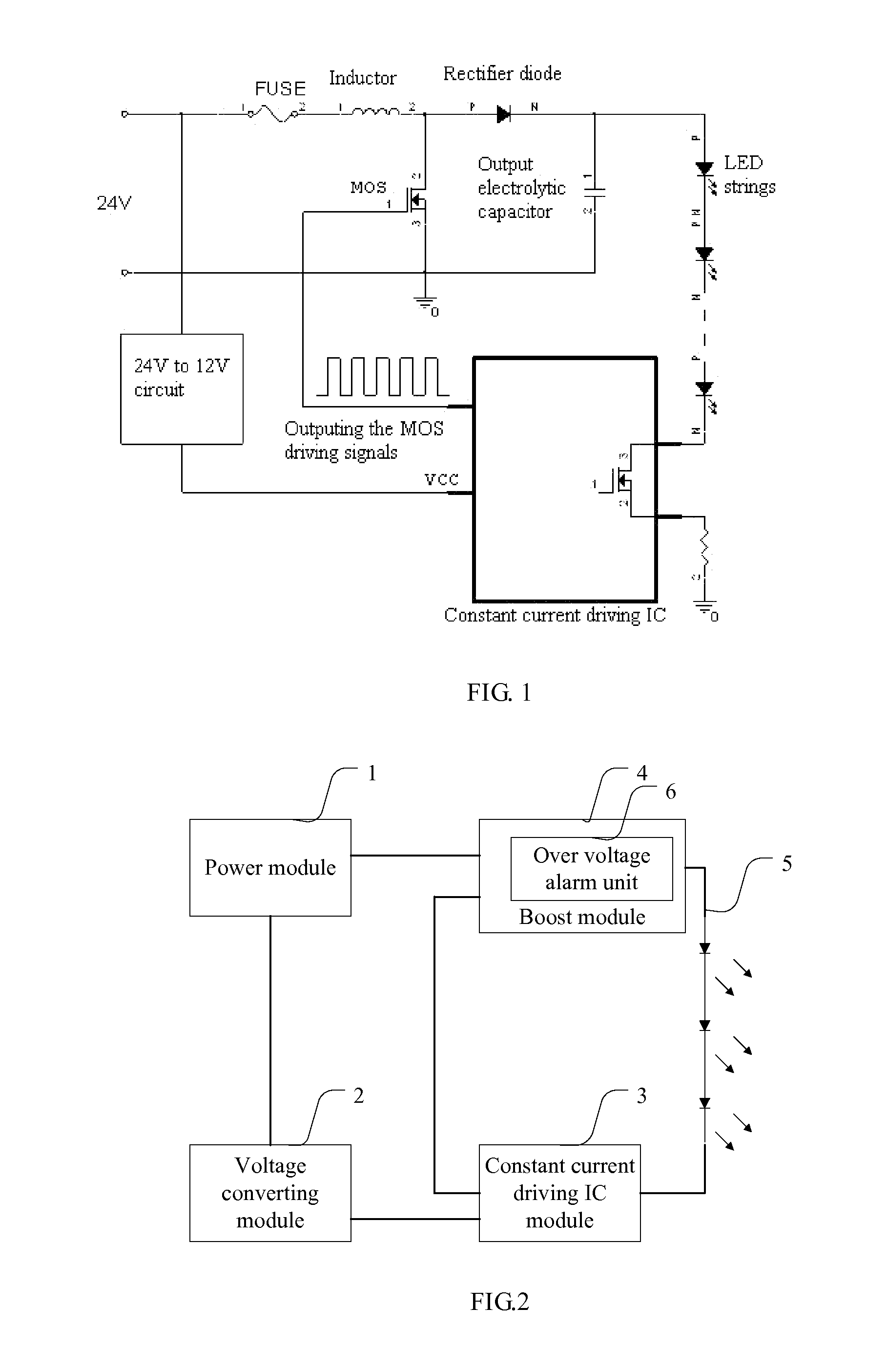
[0071]Referring to FIG. 4, it is a schematic structural diagram of the LED backlight driving circuit according to the present invention.
[0072]The third embodiment will describe the circuit structure of the LED backlight driving circuit, wherein, the power module 1 is specifically a 24V AC power, on which a fuse is connected. The voltage converting module 2 converts the 24V AC power provided by the power module 1 to a 12V AC power. One end of the constant current driving IC module 3 is connected with the LED strings 5, the MOS driving signal output terminal outputs the MOS driving signals.
[0073]More specifically, the boost module 4 comprises an energy storage inductor 41, a rectifier diode 42, a MOSFET 43 and an output electrolytic capacitor 44;[0074]the positive electrode of the rectifier diode 42 is connected with the power module 1 through the energy storage inductor 41, the negative electrode of which is connected with the LED strings 5;[0075]one end of the output electrolytic ca...
PUM
| Property | Measurement | Unit |
|---|---|---|
| voltage | aaaaa | aaaaa |
| voltage | aaaaa | aaaaa |
| voltage | aaaaa | aaaaa |
Abstract
Description
Claims
Application Information
 - R&D
- Intellectual Property
- Life Sciences
- Materials
- Tech Scout
- Unparalleled Data Quality
- Higher Quality Content
- 60% Fewer Hallucinations
Browse by: Latest US Patents, China's latest patents, Technical Efficacy Thesaurus, Application Domain, Technology Topic, Popular Technical Reports.
© 2025 PatSnap. All rights reserved.Legal|Privacy policy|Modern Slavery Act Transparency Statement|Sitemap|About US| Contact US: help@patsnap.com


