
Extrusion die for forming hollow material

a technology of extrusion die and hollow material, which is applied in the field of hollow material extrusion die, can solve the problems of increasing the extrusion speed, reducing the extrusion processing force, and reducing the life of the die, so as to prevent the bridge parts from falling off, prolong the life, and reduce the stress on the concentrated part of each bridge par

Active Publication Date: 2014-09-25
NIPPON LIGHT METAL CO LTD +1
View PDF5 Cites 8 Cited by
  • Summary
  • Abstract
  • Description
  • Claims
  • Application Information

AI Technical Summary

Benefits of technology

The present invention relates to a special extrusion die used for making hollow materials. The design of this die prevents breakage of the die and allows for high-speed extrusion and extended life even when extruding high-strength alloy materials. The die's unique structure ensures stable processing of the hollow material with high precision. This is achieved by bonding and unifying the distal-end outer peripheral surface of each bridge part of the spider and the inner peripheral surface of the holder, which reduces stress concentration on the bridge parts.

Problems solved by technology

In a case where a high-strength alloy, particularly the so-called 7000-system maximum strength aluminum alloy, is used as a material for forming a hollow material and an extruded material having a plurality of hollow parts such as a material in a sectional shape having a rectangle with two vertically parallel lines or the like is formed as a member for automobile dampers, for example, to be formed with the alloy, it is difficult to increase the speed of extrusion and to improve the life of the die since the deformation resistance thereof is higher than those of other alloy types so that the extrusion processing force becomes greater and the load for the die tools becomes greater as well.
Thus, the set amount of the billet cannot be secured.
This causes such issues that the extrusion amount of the billet is reduced, etc., so that there is naturally a limit in shortening the distance L.
Thus, there is also a limit in extending the life of the die.

Method used


Image

  • Extrusion die for forming hollow material
  • Extrusion die for forming hollow material
  • Extrusion die for forming hollow material

Examples


first embodiment

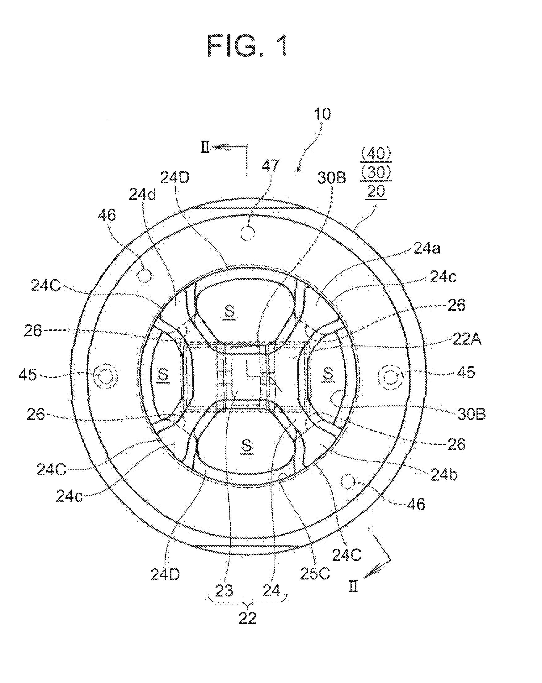
[0046]Hereinafter, an extrusion die 10 for forming a hollow material (referred simply to as an extrusion die hereinafter) according to the present invention will be described by referring to FIG. 1 to FIG. 11.

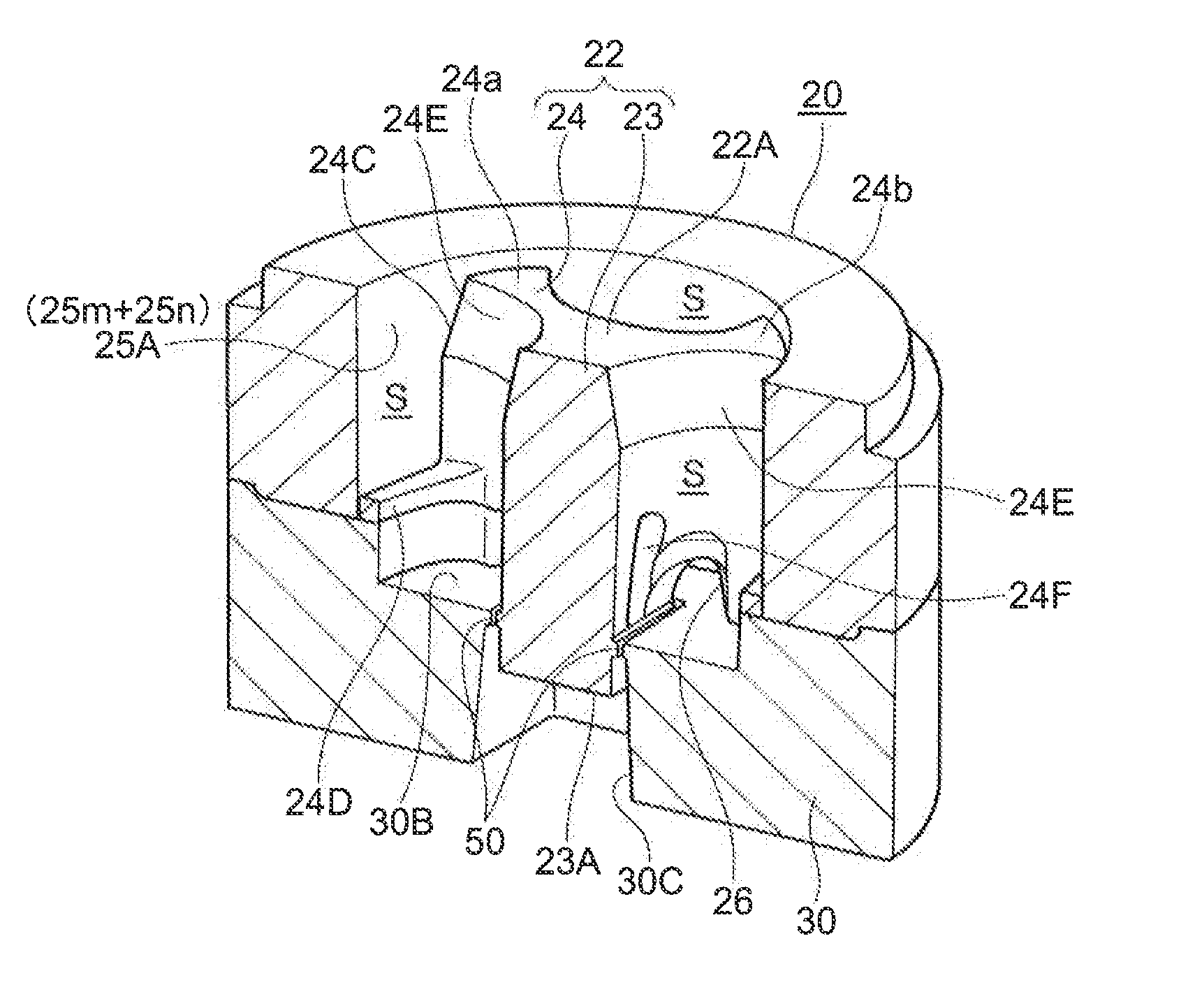
[0047]The extrusion die 10 according to the first embodiment is of a spider die type, which forms a hollow material constituted with a high-strength alloy, particularly with the so-called 7000-system maximum strength aluminum alloy. The extrusion die 10 of the embodiment forms a hollow material 1 in a sectional shape having a rectangle with two vertically parallel lines as shown in FIG. 12, for example.

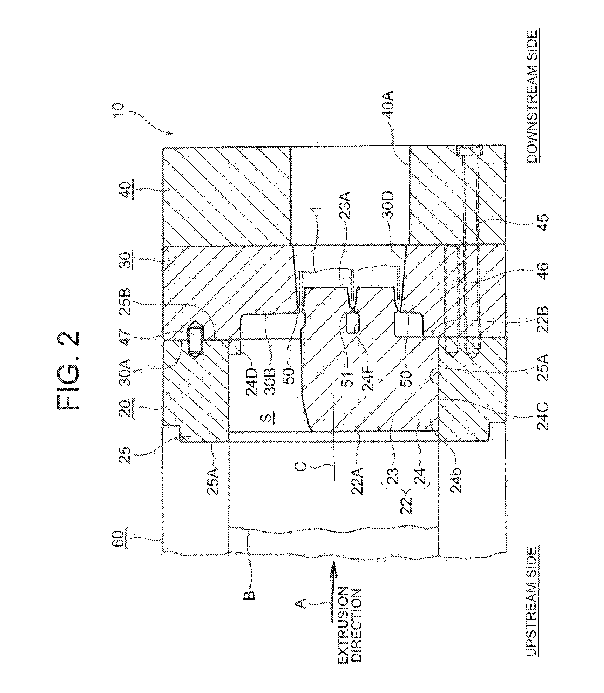
[0048]As shown in FIG. 2, the extrusion die 10 is structured by including: a male die 20 which forms an inside shape of the hollow material 1 by protruding a billet B constituted with an aluminum alloy fed from the upstream side of the extrusion direction towards the downstream side; a female die 30 which forms an outside shape of the hollow material 1; and a back die 40 for hold...

second embodiment

[0124]Next, the extrusion die according to the present invention will be described by referring to FIG. 14 to FIG. 16.

[0125]An extrusion die 10A according to the second embodiment is provided with: first to fourth bridge parts 74a to 74d corresponding to the distal-end outer peripheral surfaces 24C of the first to fourth bridge parts 24a to 24d of the extrusion die 10 according to the first embodiment; and an uneven structure 77 as well as a step structure 78 over a distal-end outer peripheral surface 74C and a bridge holding surface 75C of a holder 75.

[0126]In the second embodiment, only the uneven structure 77 and the step structure 78 are different from the first embodiment and other structures are completely the same. Thus, same reference numerals are applied to the same structures and same members, and only the different points will be described.

[0127]As shown in FIG. 14 and FIG. 15, the extrusion die 10A of the second embodiment is structured by including a male die 70 which c...

third embodiment

[0144]Next, the extrusion die according to the present invention will be described by referring to FIG. 17 and FIG. 18.

[0145]An extrusion die 10B according to the third embodiment is proposed in order to offset the pressure by bringing the surface that receives the pressure close to a position where there is a possibility of having a crack.

[0146]In the third embodiment, same reference numerals are applied to the same structures and the same members as those of the extrusion die 10 of the first embodiment, and only different points will be described.

[0147]FIG. 17 shows bonding of a distal-end outer peripheral surface 84C of a second bridge part 84b and a holder 85.

[0148]As shown in FIG. 17, a spider 82 is structured by including a mandrel 83 and a bridge part 84, and it is held by a holder 85.

[0149]Further, each of the distal-end outer peripheral surfaces 84C of the first to fourth bridge parts 84a to 84d (the second bridge part 84b in FIG. 17) constituting the bridge part 84 is form...


PUM

PropertyMeasurementUnit
sloping angleaaaaaaaaaa
angle α1aaaaaaaaaa
shapeaaaaaaaaaa

Abstract

An extrusion die is provided with a male die through which a billet is extruded from an upstream side to a downstream side and, the male die adapted for forming an inside shape of a hollow material; and a female die for holding the male die and forming an outside shape of the hollow material. The male die is formed of a spider and a holder for holding the spider. The spider is formed of a mandrel and a plurality of bridge parts for supporting the mandrel, and enabling a distal-end outer peripheral surface to engage with a bridge-holding surface. The distal-end outer peripheral surface of each of the bridge parts and the bridge-holding surface of the holder are joined by shrink-fitting.

Description

TECHNICAL FIELD[0001]The present invention is related to a hollow material forming extrusion die for forming a hollow material constituted with a high-strength alloy, particularly with the so-called 7000-system maximum strength aluminum alloy.BACKGROUND ART[0002]In general, extrusion processing of aluminum alloy and the like is high in the versatility in terms of the sectional shapes and is excellent for acquiring a hollow material formed by extrusion. Thus, it is being widely employed in these days. Recently in particular, products manufactured by extrusion processing have come to be used broadly as strong members of structural materials, mechanical components, and the like. Thus, there are increasing demands for extruded members constituted with high-strength alloys, particularly with maximum strength aluminum alloys such as the so-called 7000-system, e.g., 7075, 7N01, and 7003.[0003]As an example of a conventional extrusion die for forming a hollow material, there is known a holl...

Claims


Application Information

Patent Timeline
Patent Type & Authority Applications(United States)
IPC IPC(8): B21C25/02
CPCB21C25/02B21C23/085B21C25/00
Inventor HAYASHI, HAISEIMOCHIZUKI, YUJISAITO, SHIGENORIYUZA, KENJISATA, HIROAKISUGIHARA, HIROFUMI
Owner NIPPON LIGHT METAL CO LTD
Learn More