
Orthotic device, system and methods for addressing foot drop

a technology of orthotics and foot drop, applied in the field of orthotics, can solve the problems of decreased mobility of affected individuals, difficulty in walking, and difficulty in setting up and adjusting,

Inactive Publication Date: 2014-09-18
FOOTMIND
View PDF16 Cites 31 Cited by
  • Summary
  • Abstract
  • Description
  • Claims
  • Application Information

AI Technical Summary

Benefits of technology

The patent describes an orthotic device for addressing foot drop, which includes a securing member and support engagers. The securing member wraps around the user's leg and can be adjusted to fit different needs. The support engagers connect to eyelets in footwear or a separate foot-receiving member to provide support and prevent damage to the device. The foot-receiving member wraps around the foot and can be adjusted for size. The technical effects of this device include improved comfort and adjustability for users with foot drop.

Problems solved by technology

Because foot drop affects an individual's ability to lift his or her forefoot, it can cause difficulty walking.
A person with foot drop may drag his or her toes along the ground when walking or lift his or her knee higher than normal while walking in order to prevent the foot from dragging, resulting in what is commonly referred to as “steppage gait.” These complications may make decrease the mobility of affected individuals.
While various orthotic devices are available for treating foot drop, they are often difficult and clumsy to set up and adjust.
The complexity, weight, and lack of flexibility associated with many orthotic devices make them less convenient for affected individuals.

Method used


Image

  • Orthotic device, system and methods for addressing foot drop
  • Orthotic device, system and methods for addressing foot drop
  • Orthotic device, system and methods for addressing foot drop

Examples


Embodiment Construction

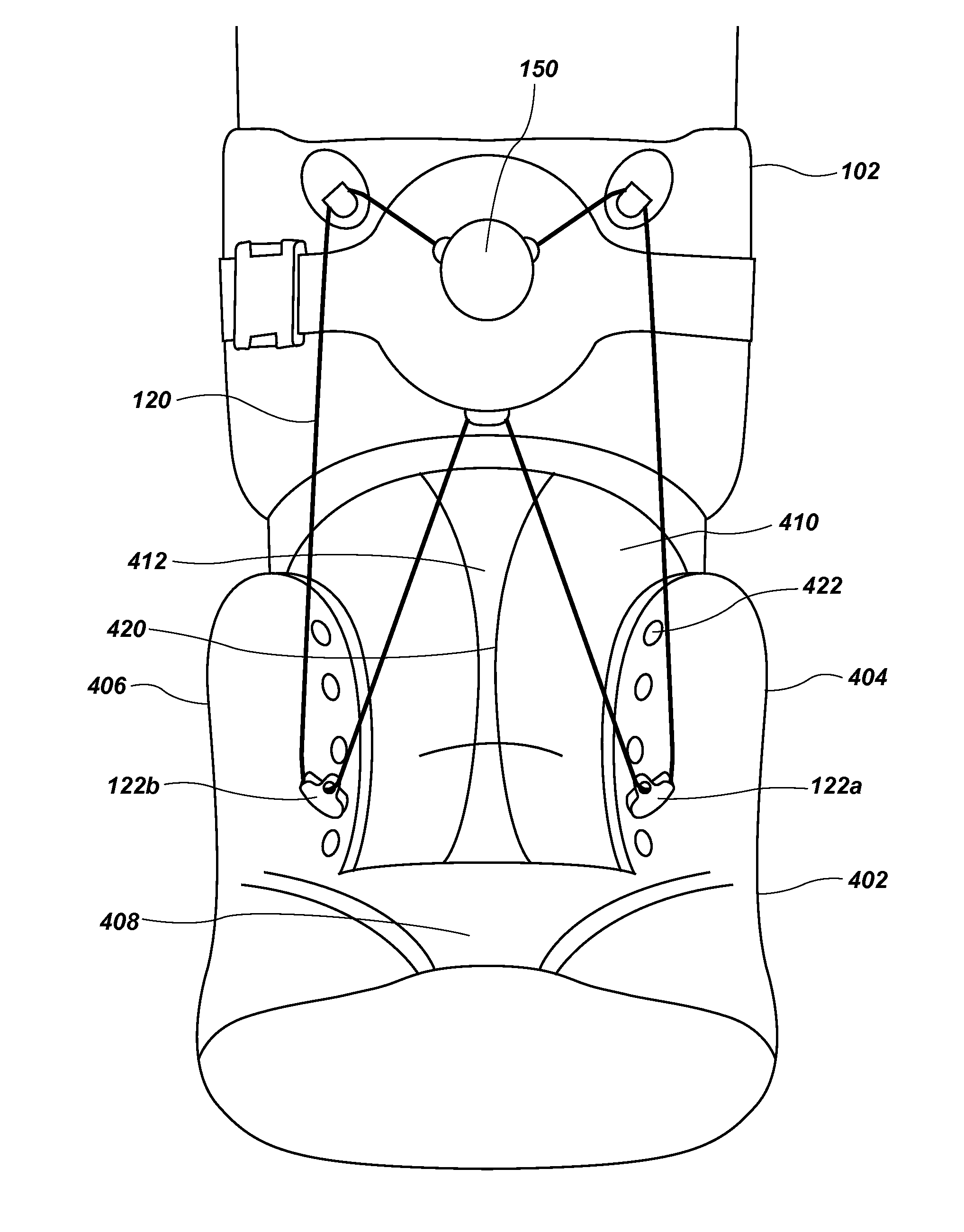
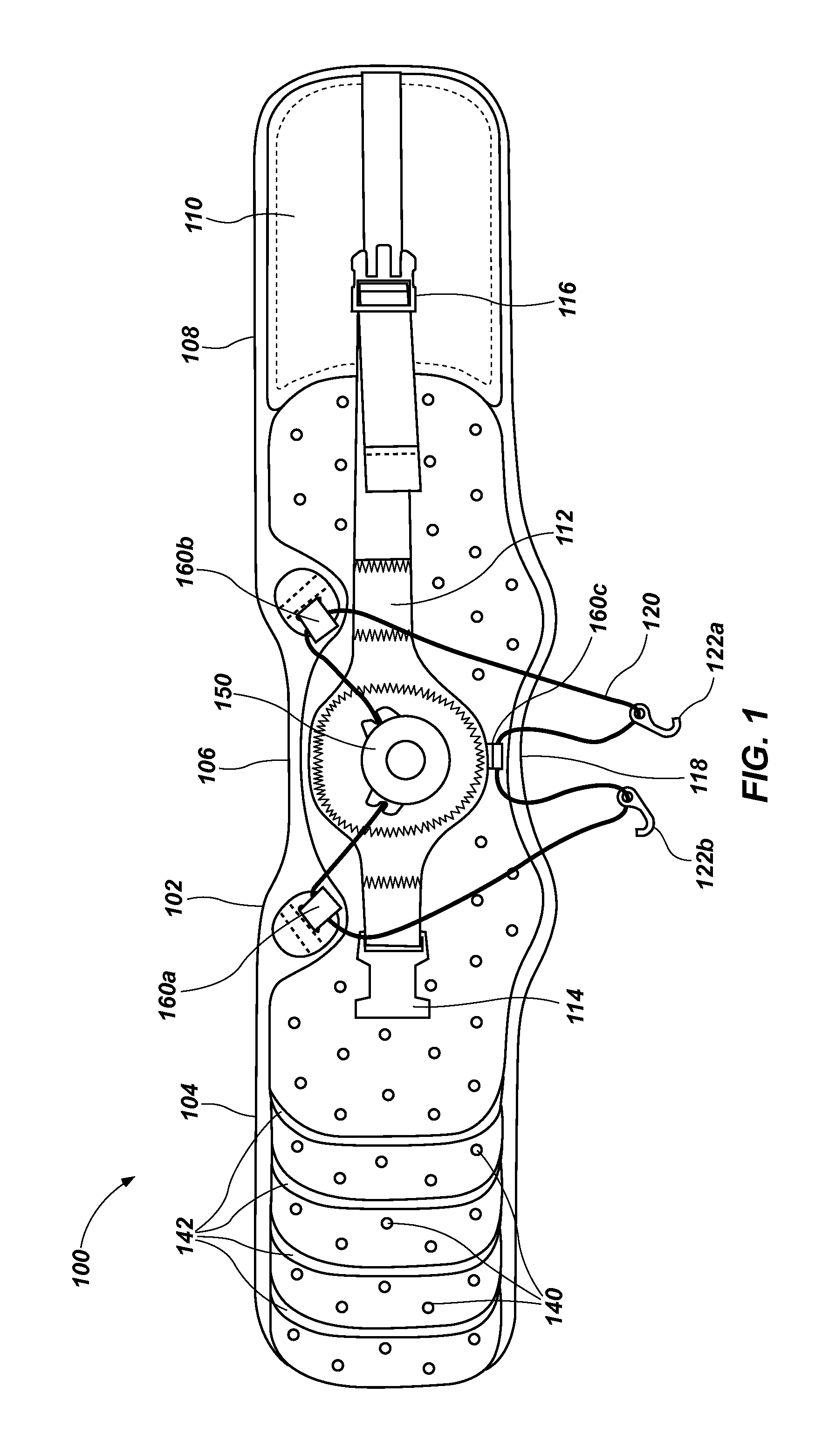
[0022]FIG. 1 illustrates one embodiment of a drop foot brace 100. The drop foot brace 100 provides support for the forefoot of the user, and can be used to treat foot drop and other conditions where the forefoot needs additional support.

[0023]The drop foot brace 100 may include a securing member 102 for securing the drop foot brace 100 to the leg of a user wearing the drop foot brace 100. Because the securing member 102 is configured to be secured to the leg of a user, its construction and the materials from which it is made may be configured to enable the securing member 102 to engage a user's leg in a desired manner. Thus, the securing member 102 may include flexible materials (e.g., fabrics, polymeric films, cushioning materials, etc.), rigid or somewhat rigid materials (e.g., plastic or metallic structural elements, form-fitting pieces, etc.) or combinations of flexible and rigid or somewhat rigid materials.

[0024]The securing member 102 includes an interior surface that faces in...


PUM


Abstract

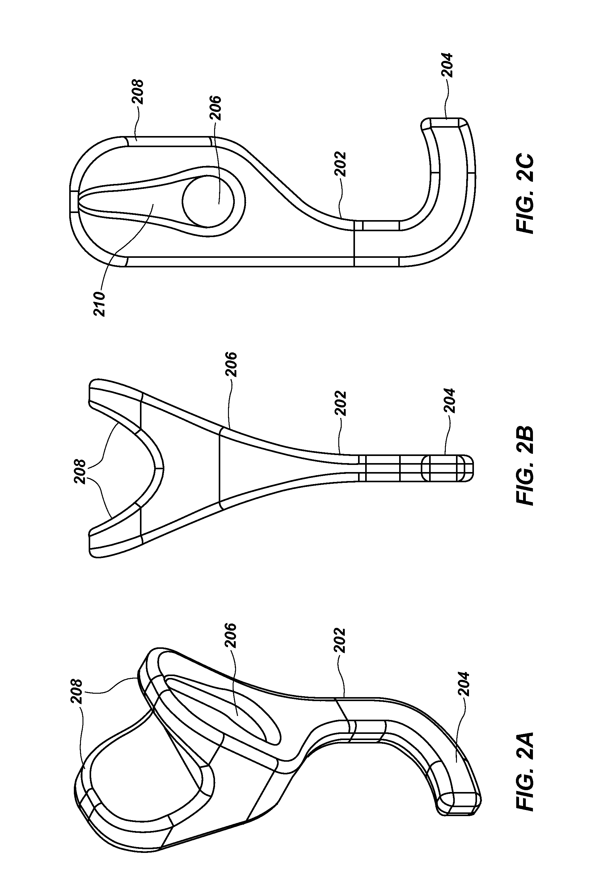
A drop foot brace includes a securing member configured to be secured to a leg of a user, a foot-receiving member and a tensioning component. The tensioning component may include an elongated element a rotatable tightening member for adjusting a tension in the elongated element and two or more support engagers associated with the elongated element. Each support engager may include a long, curved hook guide that receives the elongated element and that is configured to minimize deformation and breakage of the elongate element. In addition, each support engager may include a hook configured to engage a corresponding feature of a foot-receiving member. The foot-receiving member may comprise footwear, such as a shoe or boot, or it may be configured to enable us of the support member (and, thus, of the drop foot brace) without footwear that covers the top, or dorsal portion, of the foot. Thus, the drop foot brace may be used when an individual decides to go barefoot or when the individual wears flip-flops or other sandals. Methods for addressing drop foot are also disclosed.

Description

TECHNICAL FIELD[0001]This disclosure relates generally to orthotic devices and, more specifically, to orthotic devices that are configured for use in treating conditions that relate to feet, including foot drop. This disclosure also relates to systems and methods for treating foot drop.BACKGROUND OF RELATED ART[0002]Foot drop, which is also known as “drop foot,” is a condition in which the front part of an individual's foot, or “forefoot,” and his or her toes drop. Various causes of foot drop include weakness of the forefoot, injury to the peroneal nerve, paralysis of muscles in the anterior, or front, portion of the lower leg (i.e., the shin), or a variety of other conditions, such as a stroke, multiple sclerosis (MS), Charcot-Marie-Tooth disease, or others. The condition may be temporary or permanent, and can affect one foot or both of an individual's feet.[0003]Because foot drop affects an individual's ability to lift his or her forefoot, it can cause difficulty walking. A person...

Claims


Application Information

Patent Timeline
IPC IPC(8): A61F5/01
CPCA61F5/0127A61F5/0109
Inventor FAUX, JONATHAN ROBERT
Owner FOOTMIND
Learn More