
Reduce Motion Artifact Electrode

Inactive Publication Date: 2014-09-18
TYCO HEALTHCARE GRP LP
View PDF6 Cites 13 Cited by
  • Summary
  • Abstract
  • Description
  • Claims
  • Application Information

AI Technical Summary

Benefits of technology

The patent describes a medical electrode that has a conductive ink printed on it and can be easily attached to a patient's skin. The electrode has a foam ring that helps distribute the pressure evenly on the patient's skin. The foam ring is designed to remain securely attached to the electrode after activation. The electrode also has a conductive signal path that allows for flexibility in response to movement of the connector or the substrate. This design ensures that the patient contact portion of the electrode remains mechanically isolated from such movement while still maintaining an electrical connection. Overall, the patent provides a more comfortable and effective medical electrode for reducing patient discomfort and improving the accuracy of medical monitoring.

Problems solved by technology

As is also known, motion artifacts (e.g. spurious signals) in ambulatory recordings reduce the reliability of tests (e.g. Holter recordings and stress tests).
Motion artifacts can also cause false alarms during patient monitoring, which can reduce clinician confidence in monitoring equipment alarms and, consequently, slow response time.
One source of motion artifacts (e.g. in ECG monitoring) is relative motion between the electrode and the electrode connector.
For example, motion artifacts can be generated as a result of lateral forces applied to an electrode or a lead wire coupled to the electrode and also due to rotation of a lead wire with respect to an electrode connection point such as a stud.
While such an approach helps prevent rotation of the lead wire with respect to the electrode stud, this approach fails to provide an amount of mechanical isolation from lateral forces applied to the lead wire or electrode sufficient to eliminate or even reduce motion artifacts below desired levels.
If the electrode must be replaced, it can be difficult to detach the electrode from the lead wire due to an adhesive coupling between the lead wire and the adhesive foam of the electrode.

Method used


Image

  • Reduce Motion Artifact Electrode
  • Reduce Motion Artifact Electrode
  • Reduce Motion Artifact Electrode

Examples


Embodiment Construction

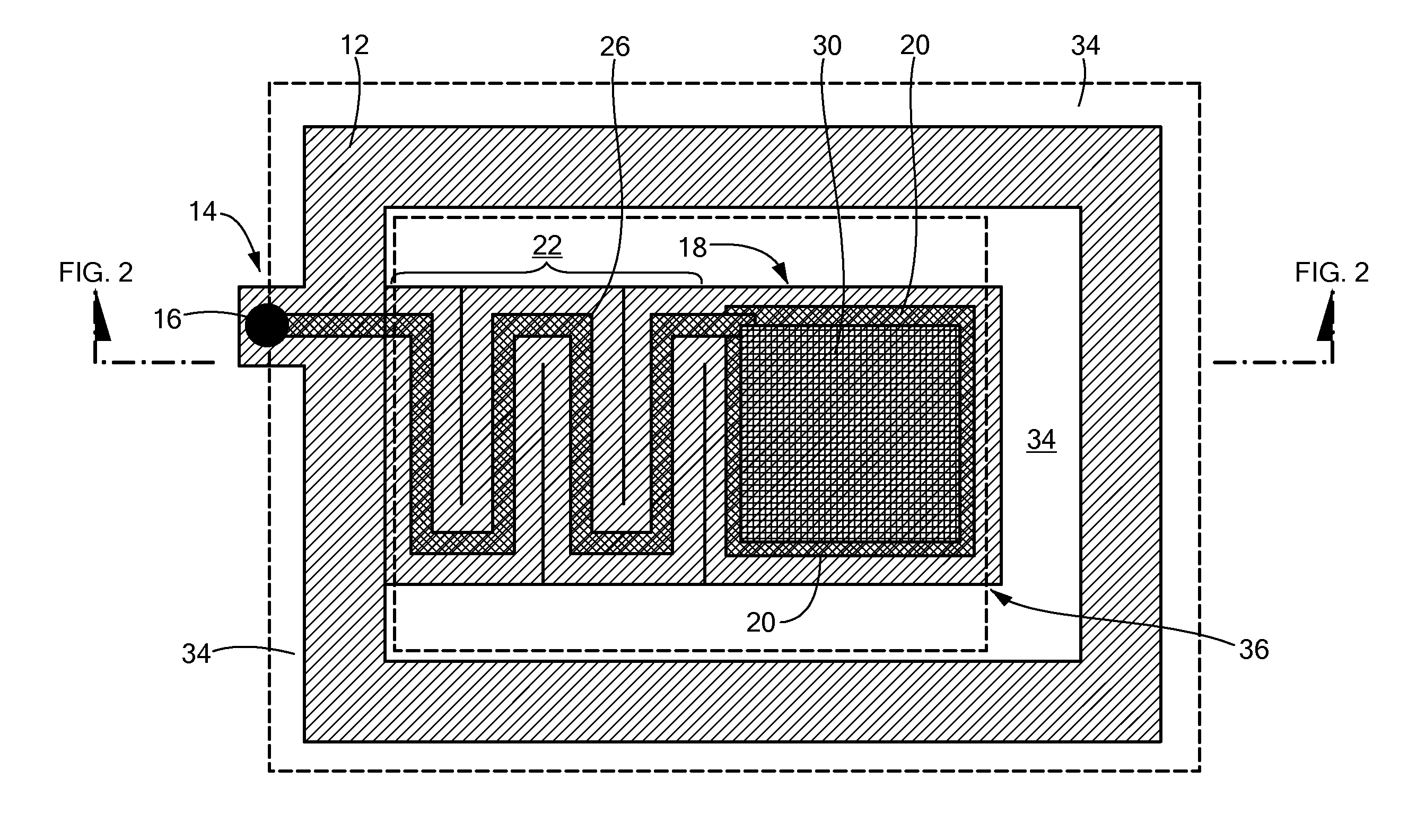
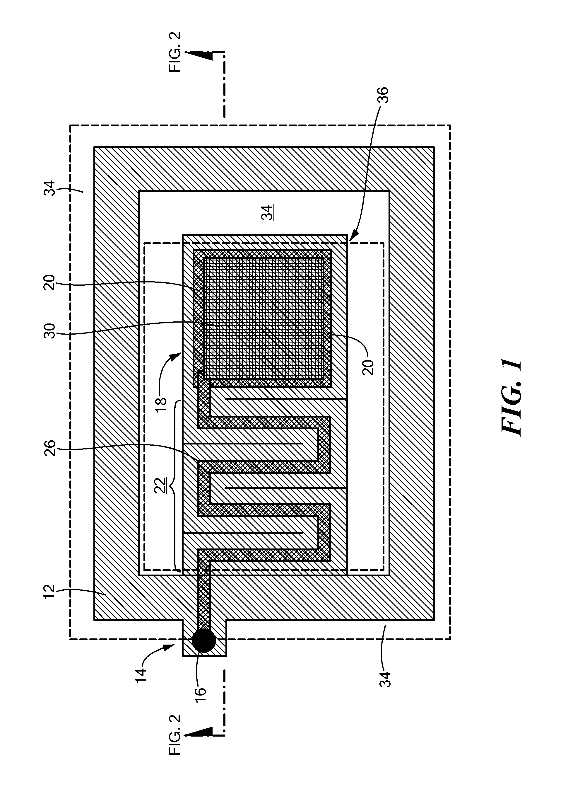
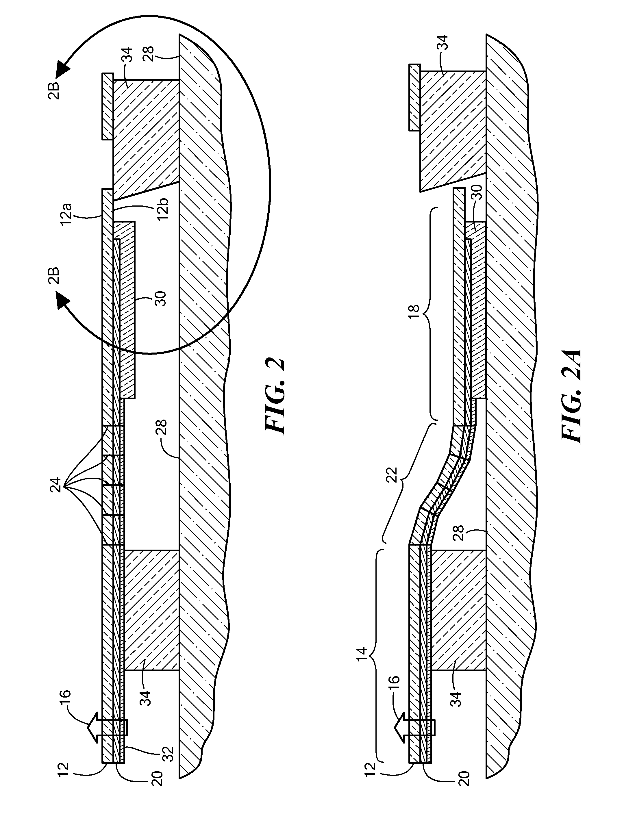
[0033]Referring now to FIGS. 1-2B in which like elements are provided having like reference designations throughout the several views, a medical electrode 10 includes a substrate 12 having first and second opposing surfaces 12a, 12b (FIG. 2A). For reasons which will become apparent hereinbelow, the type and thickness of substrate 12 is selected such that the substrate is flexible. In one embodiment, substrate 12 may be provided from a Polyethylene Terephthalate (PET) resin (such as the type manufactured by Dupont Tejjin Films and marketed under the brand name Mylar®). Those of ordinary skill in the art will appreciate, of course, that substrate 12 may be provided from other materials such as other types of polyester films or plastic sheets.

[0034]Substrate 12 has a first or connector portion 14 with a connector 16 connected thereto and a second or patient contact portion 18 having a conductive pad 20 disposed thereon. Substrate 12 also includes an isolating portion 22 which provides ...


PUM

PropertyMeasurementUnit
Forceaaaaaaaaaa
Flexibilityaaaaaaaaaa
Electrical conductoraaaaaaaaaa

Abstract

A medical electrode which mechanically isolates a conductive interface between the electrode and a patient's skin from forces applied to the lead wires or a lead wire connector is described.

Description

CROSS REFERENCE TO RELATED APPLICATIONS[0001]This application claims priority under 35 U.S.C §119 to co-pending U.S. Provisional application Ser. No. 61 / 792,760 entitled REDUCED MOTION ARTIFACT ELECRODE filed on Mar. 15, 2013 which is incorporated herein by reference for all purposes.STATEMENT REGARDING FEDERALLY SPONSORED RESEARCH[0002]Not Applicable.FIELD OF THE INVENTION[0003]The concepts, circuits and techniques described herein relate generally to medical electrodes and, more particularly, to medical electrodes for biosignal acquisition or electrical stimulation.BACKGROUND OF THE INVENTION[0004]As is known in the art, conventional medical electrodes generally include a conductive electrode member and an electrical conductor that provides an electrical interface between the electrode and various types of medical equipment, such as monitoring equipment, signal acquisition equipment and stimulating equipment. Illustrative monitoring equipment includes electrocardiograph (ECG) moni...

Claims


Application Information

Patent Timeline
IPC IPC(8): A61B5/00A61B5/0408A61B5/0416A61B5/274
CPCA61B5/6844A61B5/04087A61B5/0416A61N1/048A61B2562/187A61B2562/17Y10T29/49117A61B5/274A61B5/259A61B5/25
Inventor MEYER, PETERSELVITELLI, DAVID
Owner TYCO HEALTHCARE GRP LP
Learn More