
Diagnostic test device with improved structure

a diagnostic test and improved structure technology, applied in the field can solve the problems of insufficient fluid application or device flooding, lack of ergonomically favorable structure of known point of care or over the counter diagnostic test devices, and limited user interface of diagnostic test devices, so as to improve ergonomics and facilitate use of devices

Active Publication Date: 2014-09-18
CHURCH & DWIGHT CO INC
View PDF7 Cites 2 Cited by
  • Summary
  • Abstract
  • Description
  • Claims
  • Application Information

AI Technical Summary

Benefits of technology

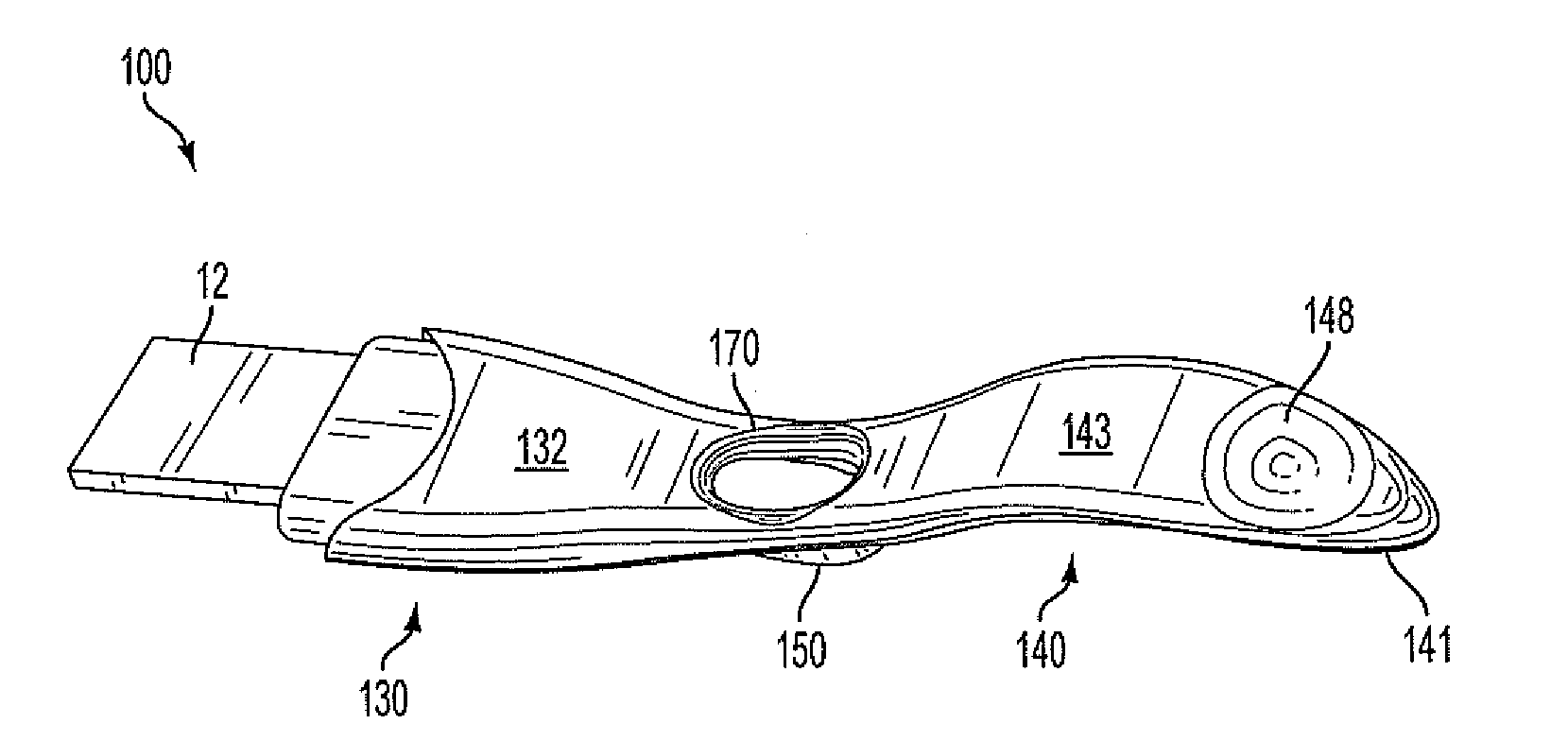
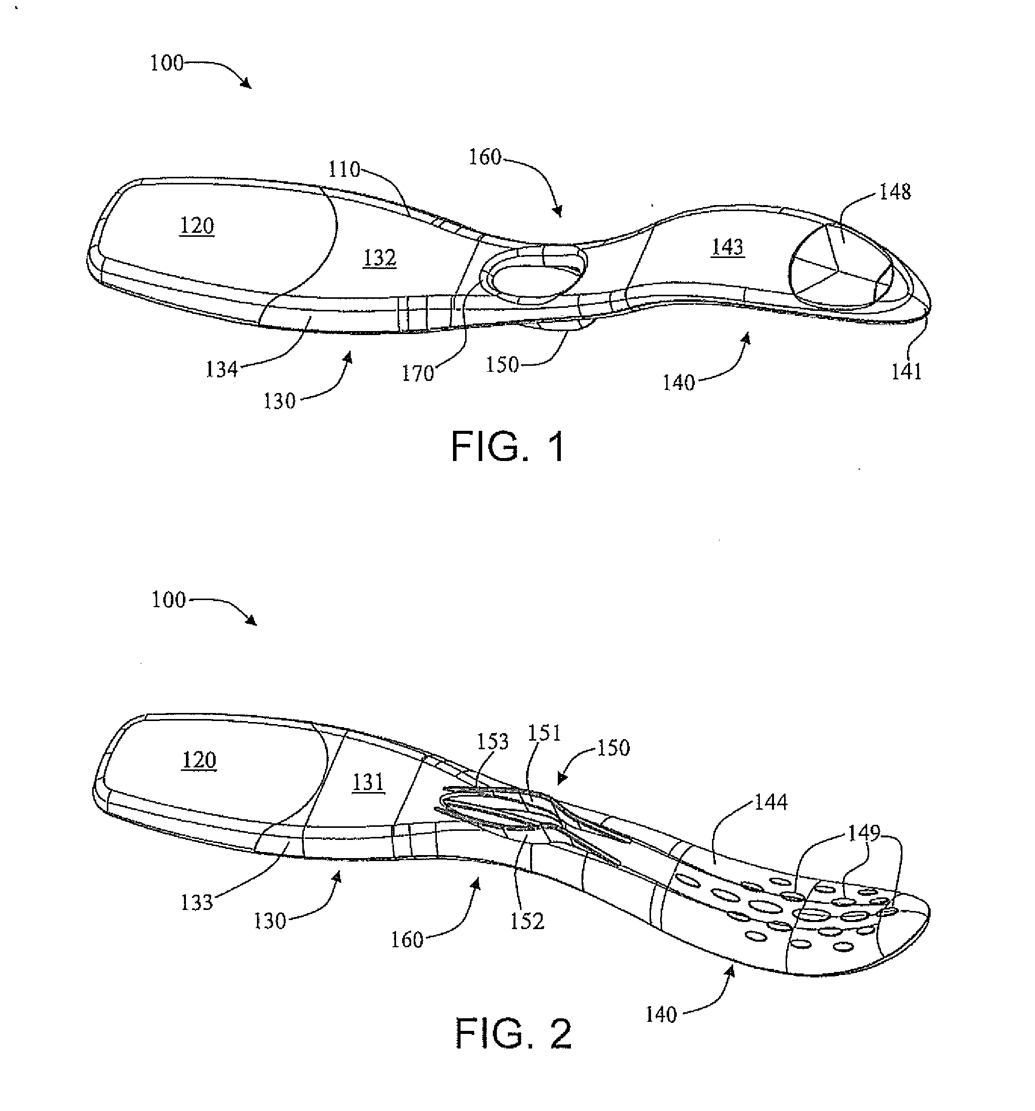
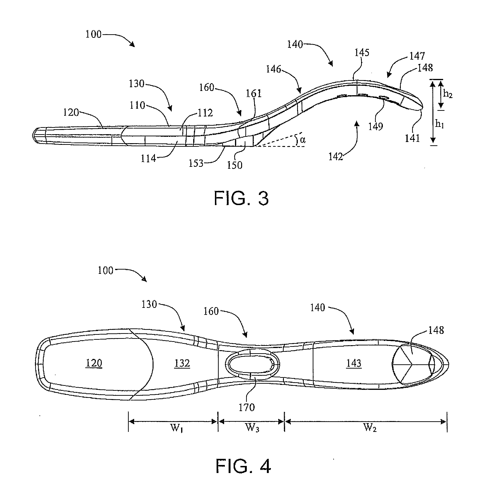
The present disclosure presents diagnostic test devices that have various elements useful for carrying out an assay and providing information related to the assay in an informative display. For example, a pregnancy test device can be provided that includes elements for carrying out a test on a fluid sample to identify the presence of human chorionic gonadotropin (hCG) indicative of pregnancy. The diagnostic test devices are designed to improve ergonomics and ease of use in different methods. Additionally, the diagnostic test devices have a base member that can be attached to a curved lower surface of the housing and can provide support to the housing when placed on a flat surface. The base member has a horizontal support surface that increases the support length of the housing by about 5% or greater. The angle between the horizontal support surface and the curved lower surface of the housing can be about 5° to about 45°. The horizontal support surface can have a length of about 10 mm to about -30 mm. The curved base member walls can define a width WBM1 at the forward section, a width WBM2 at a central section, and a width WBM3 at the rearward section. The different widths can be defined by the formula WBM1BM2>WBM3.

Problems solved by technology

Nevertheless, user interface with diagnostic test devices remain limited.
In particular, known point of care or over the counter diagnostic test devices lack an ergonomically favorable structure.
As such, it is often difficult for a user to handle the device during application of the test fluid, such as from a urine stream, which can lead to either insufficient fluid application or device flooding.

Method used


Image

  • Diagnostic test device with improved structure
  • Diagnostic test device with improved structure
  • Diagnostic test device with improved structure

Examples


Embodiment Construction

[0045]The present disclosure now will be described more fully hereinafter with reference to specific embodiments and particularly to the various drawings provided herewith. Indeed, the disclosure may be embodied in many different forms and should not be construed as limited to the embodiments set forth herein; rather, these embodiments are provided so that this disclosure will satisfy applicable legal requirements. As used in the specification, and in the appended claims, the singular forms “a”, “an”, “the”, include plural referents unless the context clearly dictates otherwise.

[0046]In one aspect, the present disclosure relates to a test device, such as an over-the-counter (OTC), personal use, or point of care (POC) test device, for detecting an analyte in a sample. The device generally includes components suitable for carrying out an assay, such as a lateral flow assay, and also includes components suitable for communicating information relating to the assay to an individual. The ...


PUM


Abstract

The present disclosure relates to diagnostic test devices that provide increased comfort and ease of use. The diagnostic test device can include a test member, such as a lateral flow assay test strip. The test device can further comprise a housing that comprises a substantially arch shaped handle. The housing of the test device can comprise a base member that is attached to a curved lower surface of the housing and that can improve stability of the device in an upward facing position as well as enable angled positioning of the device relative to a flat, horizontal surface. The curvature of the test device in particular can provide secure handling of the device while also improving ease and comfort of use thereof. The disclosure further relates to methods of determining the presence of an analyte in a fluid sample and methods for evaluating a test result of a personal use diagnostic test device.

Description

FIELD OF THE DISCLOSURE[0001]The present disclosure relates to diagnostic test devices that provide increased ease of use. More particularly, the test devices include structural and functional elements that improve user handling and evaluation of the device.BACKGROUND[0002]Many types of ligand-receptor assays have been used to detect the presence of various substances in body fluids, such as urine, saliva, or blood. Some commercially available assays are designed to make a quantitative determination, but in many circumstances all that is required is a qualitative positive / negative indication. Examples of such qualitative assays include blood typing, pregnancy testing, and many types of urinalysis.[0003]U.S. Pat. No. 6,485,982, which is incorporated herein by reference in its entirety, describes a diagnostic test cell or device formed of an elongated outer casing which houses an interior permeable material (such as glass fiber) capable of transporting an aqueous solution by capillary...

Claims


Application Information

Patent Timeline
IPC IPC(8): G01N33/53
CPCG01N33/5302A61B10/0045G01N33/54366G01N33/558A61B2560/0406A61B2560/0431A61B2560/0425G01N33/54388
Inventor SNOWDEN, TIMOTHYBUENTELLO, KRISTENTOMASELLO, ASHLEYMOHAMED, DEAN M.
Owner CHURCH & DWIGHT CO INC
Learn More