
Dental crowns and bridges and method of making same

Active Publication Date: 2014-09-18
GLOBAL DENTAL SCI
View PDF3 Cites 14 Cited by
  • Summary
  • Abstract
  • Description
  • Claims
  • Application Information

AI Technical Summary

Benefits of technology

The methods described in this patent solve problems with current methods for making dental prostheses, such as inconsistencies in the application of human energy to the outer layer of the prosthesis and reduced labor costs.

Problems solved by technology

A problem with the conventional feldspathic PFM is that the porcelain is very durable and tends to wear opposing natural dentition.
In addition, metal can show through around the marginal edges of the porcelain, resulting in there being the perceived appearance of “black” lines at the margins.
The problem with many of these all-ceramic products was that they lacked strength, especially needed in the posterior teeth.
The cost of milling zirconia by CAD-CAM based tooling was relatively expensive at the initial stage.
However, the cost of milling equipment and software continued to decrease, such that more dental laboratories started using zirconia as the primary substructure for crowns.
The primary problem with zirconia is the inherent color: it is bright white and does not have the appearance of natural teeth.
Since most teeth are not completely white, some skill and cost is required to overlay porcelain on the zirconia in order to deliver an esthetic natural appearing tooth.
However, certain problems remain to be solved with this manufacturing method and / or with the dental prostheses made by it.
One remaining problem is that the zirconia is very abrasive to the opposing dentition, which was the original problem with conventional feldspathic PFMs.
However, a problem with this approach is that it requires skills and labor to layer the porcelain by hand, which makes the crown more expensive to produce.

Method used


Image

  • Dental crowns and bridges and method of making same
  • Dental crowns and bridges and method of making same
  • Dental crowns and bridges and method of making same

Examples


Embodiment Construction

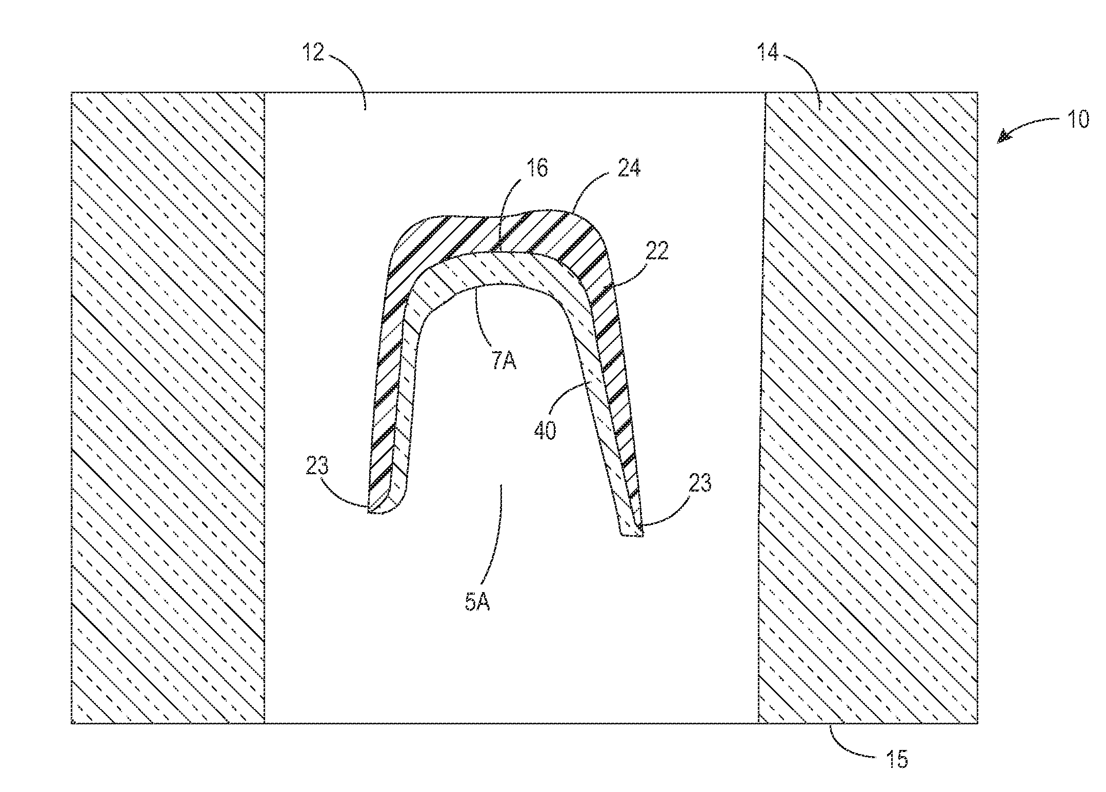
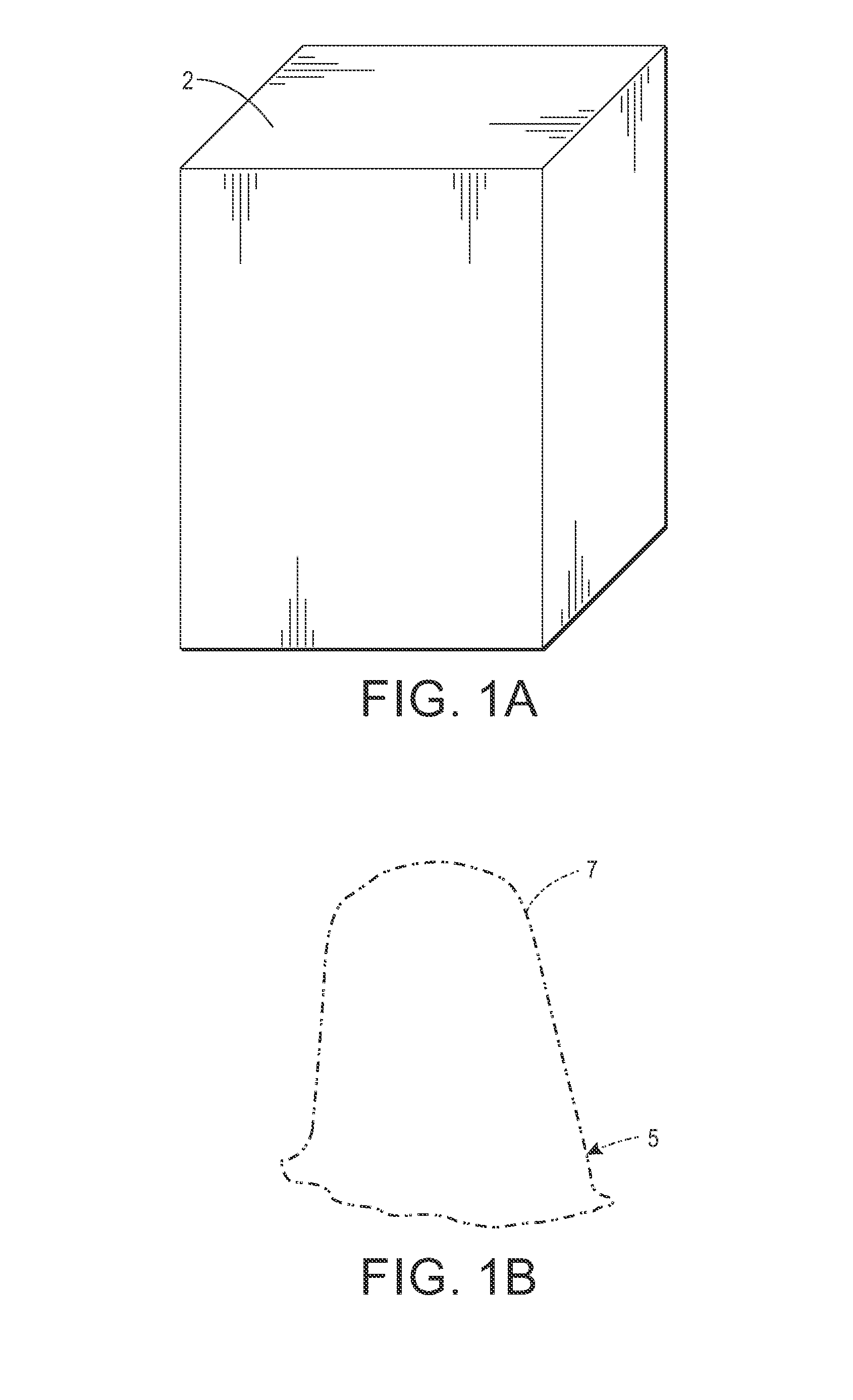
[0032]For a general understanding of the present invention, reference is made to the drawings. In the drawings, like reference numerals have been used throughout to designate identical elements. In the following disclosure, certain components may be identified with adjectives “top,”“upper,”“bottom,”“lower,”“left,”“right,” etc. These adjectives are provided in the context of the orientation of the drawings, which is arbitrary. The description is not to be construed as limiting the methods and apparatus disclosed herein to use in a particular spatial orientation. The instant methods and apparatus may be used in orientations other than those shown and described herein.

[0033]As used herein, the term or acronym “CAD-CAM” refers to Computer Aided Design and Computer Aided Manufacturing. Depending upon the context of use, the term may be referring to a computer software program for the design of an article such as a tooth or denture, or a computer software program for the manufacture of an...


PUM

PropertyMeasurementUnit
Pressureaaaaaaaaaa
Flow rateaaaaaaaaaa
Shapeaaaaaaaaaa

Abstract

Dental prostheses and methods for making them are disclosed. In one embodiment, a method comprises a sequence of steps including milling a cavity in a block of a coping material, filling the cavity with a green ceramic material, milling a portion of the green ceramic material away to leave a layer of green ceramic material on an occlusal surface formed in the coping material, milling the underside of the block of coping material to form the coping with green ceramic material, and sintering the coping with green ceramic material to complete the prosthesis. The milling steps may be performed by a computer-controlled mill. The computer may execute a CAD-CAM program that includes data from a three dimensional model of a tooth that is to receive the prosthesis. The dental prosthesis may be a dental crown or a dental bridge.

Description

CROSS-REFERENCE TO RELATED PATENT APPLICATIONS[0001]This application claims priority from U.S. provisional patent Application No. 61 / 792,254 filed Mar. 15, 2013, the disclosure of which is incorporated herein by reference.BACKGROUND[0002]1. Technical Field[0003]Dental prostheses and apparatus and methods of manufacturing them. In particular, a dental crowns and bridges, and an associated CAD-CAM method for making the crowns and bridges.[0004]2. Description of Related Art[0005]Dentures, partial dentures, dental crowns, and dental bridges are prosthetic articles that are made to replace some or all of a person's natural teeth. A dental crown is a rigid fitting that completely encloses or caps a tooth or multiple teeth. A dental bridge is an artificial tooth or teeth that replaces missing natural teeth and that is joined to adjacent remaining teeth.[0006]When a dentist diagnoses that his / her patient has a need for a dental crown or bridge, he / she will generally prepare the tooth (or te...

Claims


Application Information

Patent Timeline
IPC IPC(8): A61C13/00A61C5/08
CPCA61C13/0004A61C5/08A61C13/0006A61C13/0022A61C13/081A61C13/09A61C5/70A61C5/77Y10T29/49567A61C13/0003A61C13/083
Inventor HOWE, DEVON O.
Owner GLOBAL DENTAL SCI
Learn More