
Temperature control method for proton exchange membrane fuel cell system for vehicle

A technology of fuel cell system and temperature control method, which is applied in the direction of fuel cells, fuel cell additives, fuel cell heat exchange, etc., and can solve problems such as difficulty in meeting temperature control requirements, strong time-varying fuel cells, and small application range of models, etc. Achieve the effects of avoiding adverse effects, fast dynamic response, and avoiding frequent start and stop

Active Publication Date: 2021-04-06
HAIDRIVER (QINGDAO) ENERGY TECH CO LTD
View PDF9 Cites 15 Cited by
  • Summary
  • Abstract
  • Description
  • Claims
  • Application Information

AI Technical Summary

Problems solved by technology

[0003] The invention patent with the publication number [CN 111129550 A] discloses a PID control method for a fuel cell system, which uses a traditional PID control algorithm to control the temperature of the fuel cell; however, the fuel cell is a complex nonlinear time-varying system with fixed parameters The advanced PID control algorithm is difficult to meet the temperature control requirements under complex and variable working conditions
The invention patent with the publication number [CN111403779 A] discloses a model-based adaptive temperature control method, which controls the temperature of the stack and the inlet temperature of the circulating coolant by adjusting the mass flow rate of the stack coolant and the opening coefficient of the bypass valve. However, the model-based control method relies on an accurate mathematical model, and it is difficult to obtain an accurate model, and the time-varying nature of the fuel cell is strong, so the scope of application of the model is small

Method used


Image

  • Temperature control method for proton exchange membrane fuel cell system for vehicle
  • Temperature control method for proton exchange membrane fuel cell system for vehicle
  • Temperature control method for proton exchange membrane fuel cell system for vehicle

Examples


Embodiment Construction

[0044] In order to understand the above-mentioned purpose, features and advantages of the present invention more clearly, the present invention will be further described below in conjunction with the accompanying drawings and embodiments. Many specific details are set forth in the following description to facilitate a full understanding of the present invention. However, the present invention can also be implemented in other ways than those described here. Therefore, the present invention is not limited to the specific embodiments disclosed below.

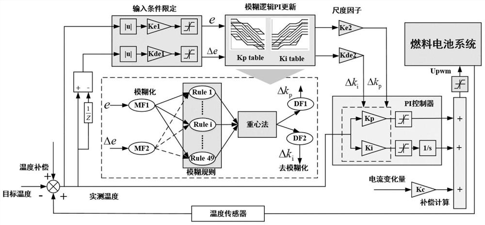
[0045] This embodiment proposes a temperature control method for a proton exchange membrane fuel cell system for vehicles, such as figure 1 shown, including the following steps:

[0046] Step S1, measuring the inlet temperature of the stack coolant, and setting the target coolant inlet temperature;

[0047] Step S2, calculate the temperature deviation: make the difference between the actual value measured by the temperature sensor...


PUM


Abstract

The invention discloses a temperature control method for a proton exchange membrane fuel cell system for a vehicle, which comprises the following steps of: detecting the inlet temperature of a cooling loop of a fuel cell stack by using a temperature sensor, inputting the inlet temperature into a controller, and achieving cooling fan control based on the controller, wherein the cooling fan control comprises fuzzy logic adaptive proportional integral control and feedforward compensation control, a gain parameter of the proportional integral control is adaptively updated by a fuzzy logic algorithm, the load current of the fuel cell is used as disturbance and is used for feedforward compensation, and meanwhile, the opening degree of the fan is determined by the total heat dissipating capacity demand and the number of cooling fans; and finally, inputting a control signal output by the controller into an actuator of a thermal management subsystem to control the temperature of the cooling inlet of the fuel cell stack. The temperature control strategy provided by the invention can reduce the temperature fluctuation during the operation of the vehicle fuel cell engine, improve the system performance and prolong the service life.

Description

technical field [0001] The invention belongs to the technical field of fuel cells, in particular to a method for controlling the temperature of a proton exchange membrane fuel cell system for vehicles. Background technique [0002] Fuel cell vehicles are an important branch of new energy vehicles. Due to their advantages such as fast hydrogen filling, high system efficiency, low noise, and zero emissions, they are considered to be one of the ultimate solutions for future vehicles. Fuel cells work under dynamic loads. Temperature fluctuations of fuel cell systems have an important impact on engine performance and service life. Long-term low temperature conditions can easily cause fuel cell stack flooding. Long-term flooding failures will cause fuel starvation and eventually lead to Irreversible decay of the catalyst layer. At the same time, excessive temperature causes excessive thermal stress on the exchange membrane, and pinholes or cracks will spontaneously form under str...

Claims


Application Information

Patent Timeline
Patent Type & Authority Applications(China)
IPC IPC(8): H01M8/0432H01M8/04701H01M8/04992
CPCH01M8/04358H01M8/04701H01M8/04992Y02E60/10H01M2250/20H01M2008/1095H01M8/04768Y02E60/50H01M8/04014H01M8/04723H01M2220/20
Inventor 朱维吴伟谢佳平
Owner HAIDRIVER (QINGDAO) ENERGY TECH CO LTD
Learn More