
Motion compensated second pass metal artifact correction for ct slice images

a technology of image artifact correction and motion compensation, applied in the field of apparatus for correcting cross sectional slice images for image artifacts, can solve problems such as image artifacts, and achieve the effect of reducing artifacts

Active Publication Date: 2014-09-18
KONINKLIJKE PHILIPS ELECTRONICS NV
View PDF8 Cites 23 Cited by
  • Summary
  • Abstract
  • Description
  • Claims
  • Application Information

AI Technical Summary

Benefits of technology

The patent describes an apparatus for improving the quality and accuracy of medical images, particularly those acquired usingCT scanners. The apparatus uses a reconstruction algorithm and information provided by image artifacts (distortions and blurs) in the images to create correction images with less distortion and blurring. This is particularly useful when there are metallic objects in the body, such as needles or catheters, that are moving during the acquisition process. By using the information from the image artifacts, the apparatus can provide a more accurate representation of the location of these objects and improve the overall quality of the medical images.

Problems solved by technology

Unfortunately, small but non-negligible motion of the metallic implant inside the gating window may still lead to image artifacts.

Method used


Image

  • Motion compensated second pass metal artifact correction for ct slice images
  • Motion compensated second pass metal artifact correction for ct slice images
  • Motion compensated second pass metal artifact correction for ct slice images

Examples


Embodiment Construction

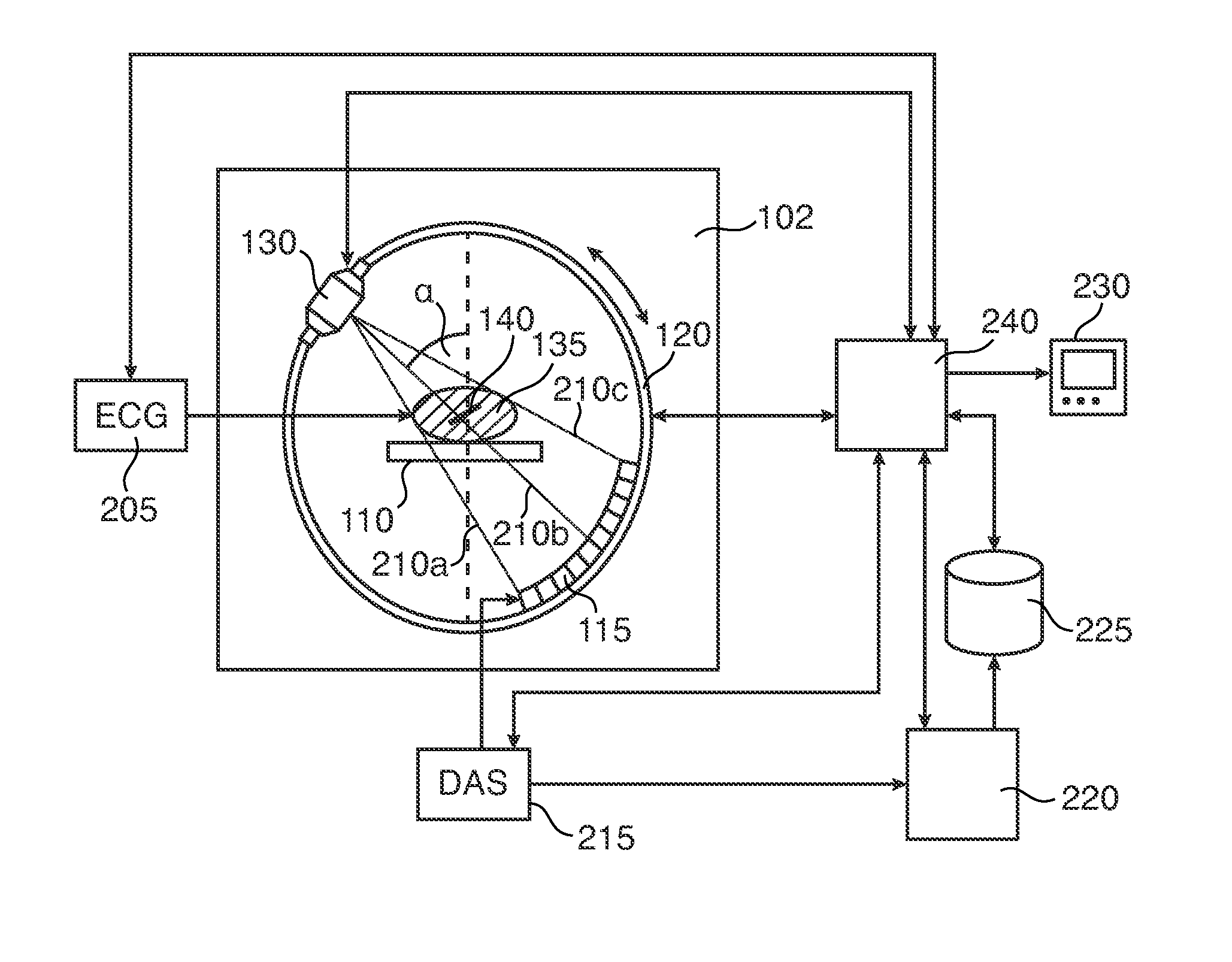
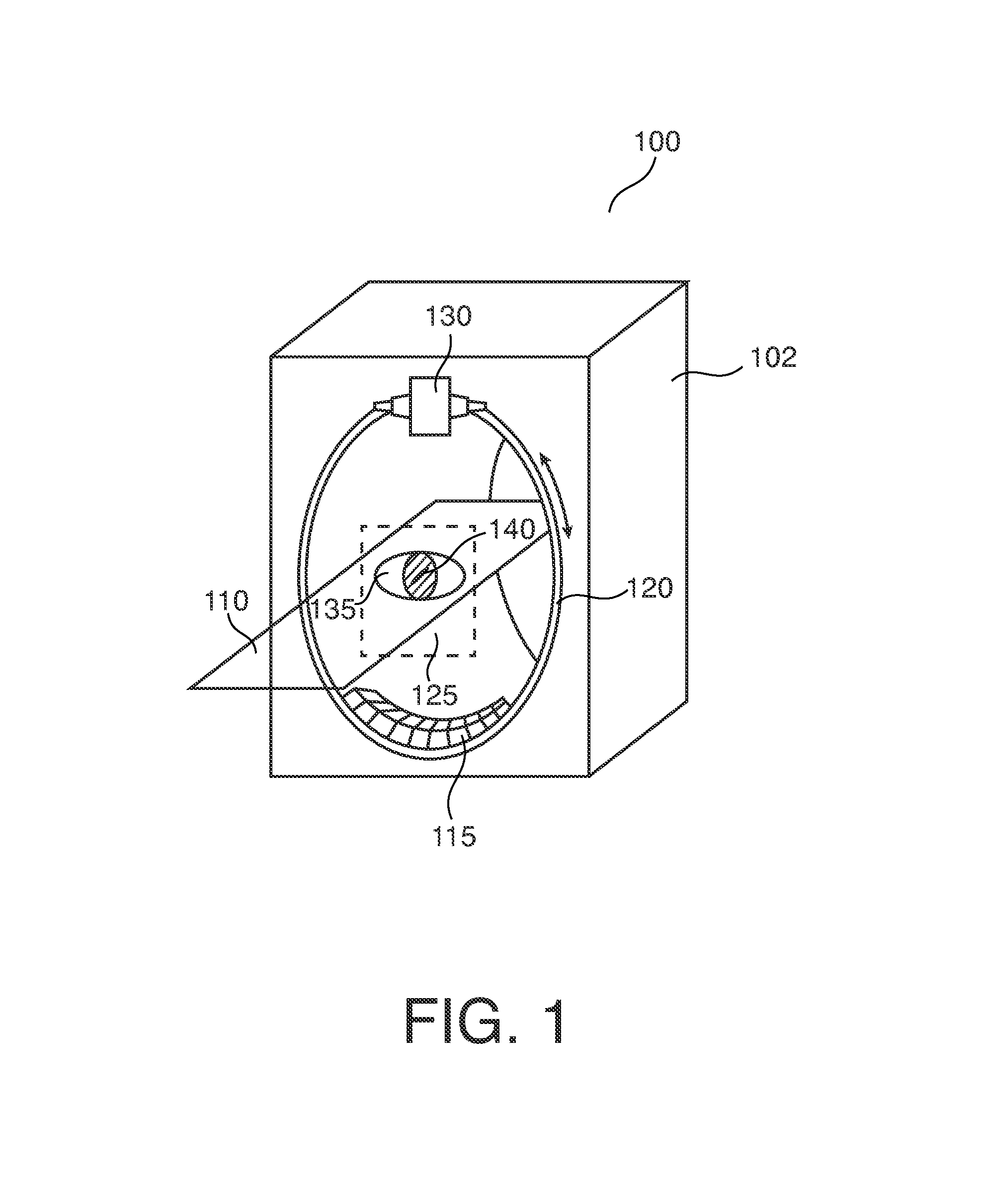
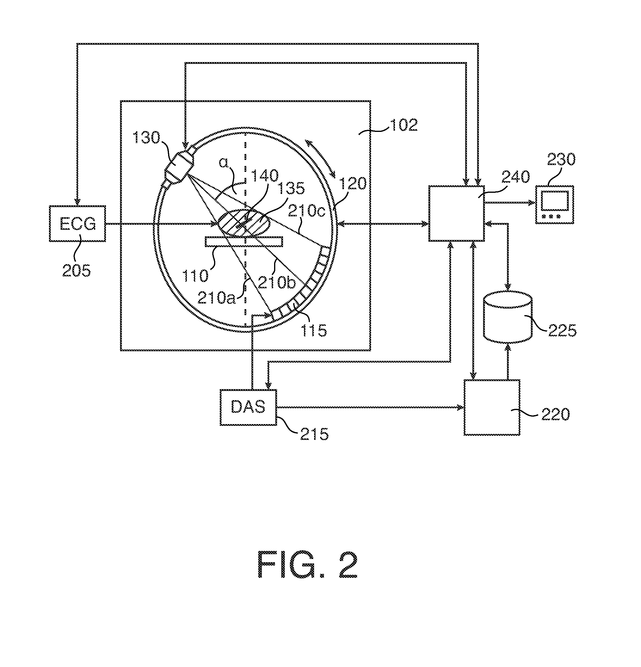
[0045]With reference to FIG. 1, an exemplary CT scanner system (“third generation”) is shown. The system 100 comprises a frame 102 having a bore. A gantry 120 is rotatably arranged inside the bore as a rigid cylinder structure. Gantry 120 includes in rigid and opposed relationship an x-ray tube 130 and a detector array 115. An examination table 110 is provided extending into gantry 102 and passing through the center of gantry 120 cylinder. An object of interest such as a human heart 135 of a patient lying on the table 110 is positioned at the center point of gantry 120. Heart 135 incorporates a metallic object such as a catheter guiding wire 140. Because of the positioning of the heart 135 and thus wire 140 at the center or “focal point” of gantry 120, wire 140 is positioned at all times throughout the scan run between X-tray tube 130 and detector array 115 whilst gantry 120 rotates around wire 140. Because of the rigid arrangement in the gantry 120, x-ray tube 130 and detector 115 ...


PUM


Abstract

An apparatus and a method for correcting a CT slice image for an image artifact (330) caused by the motion of a high attenuation part (140) in an object (135) of interest. The CT slice image is based on projection images (310a,b). The apparatus and method uses a footprint (315a,b) of the part in each of the projection images (310a,b).

Description

FIELD OF THE INVENTION[0001]The invention relates to an apparatus for correcting a cross sectional slice image for an image artifact, to a method of correcting a cross sectional slice image for an image artifact, to a medical image processing system for correcting a cross sectional slice image for an image artifact, to computer product and to a computer readable medium.BACKGROUND OF THE INVENTION[0002]An increasing number of patients who undergo a cardiac CT (computed tomography) examination have metallic implants in their hearts, such as artificial heart valves, bi-ventricular pacemakers, stents, Amplatzer devices or similar. Prospectively gated cardiac CT scanning delivers good image results for soft tissue because the scans are carried out during the cardiac resting phase to so minimize motion-caused image artifacts. Unfortunately, small but non-negligible motion of the metallic implant inside the gating window may still lead to image artifacts. A cardiac computer tomography syst...

Claims


Application Information

Patent Timeline
Patent Type & Authority Applications(United States)
IPC IPC(8): G06T5/00G06K9/62G06T7/00
CPCA61B6/032A61B6/5264A61B6/12A61B6/503G06T11/008A61B6/541G06K9/6201G06T5/00G06T7/0012A61B6/5241G06F18/22
Inventor GRASS, MICHAELSCHMITT, HOLGERSCHAFER, DIRK
Owner KONINKLIJKE PHILIPS ELECTRONICS NV
Learn More