
Harmonic cancellation circuit for an RF switch branch

a technology of harmonic cancellation circuit and switch branch, which is applied in the direction of frequency selective two-port network, oscillation generator, pulse technique, etc., can solve the problem that the harmonics generated in the power amplifier (pa) and front end (fe) switch are not attenuated sufficiently to prevent receiver desensitization, and the art methods such as adding static notch filters into the tx path may not be directly applicable to antenna tuning components, and achieve difficult or impossible to implement diplexers

Active Publication Date: 2014-09-18
QORVO US INC
View PDF13 Cites 33 Cited by
  • Summary
  • Abstract
  • Description
  • Claims
  • Application Information

AI Technical Summary

Benefits of technology

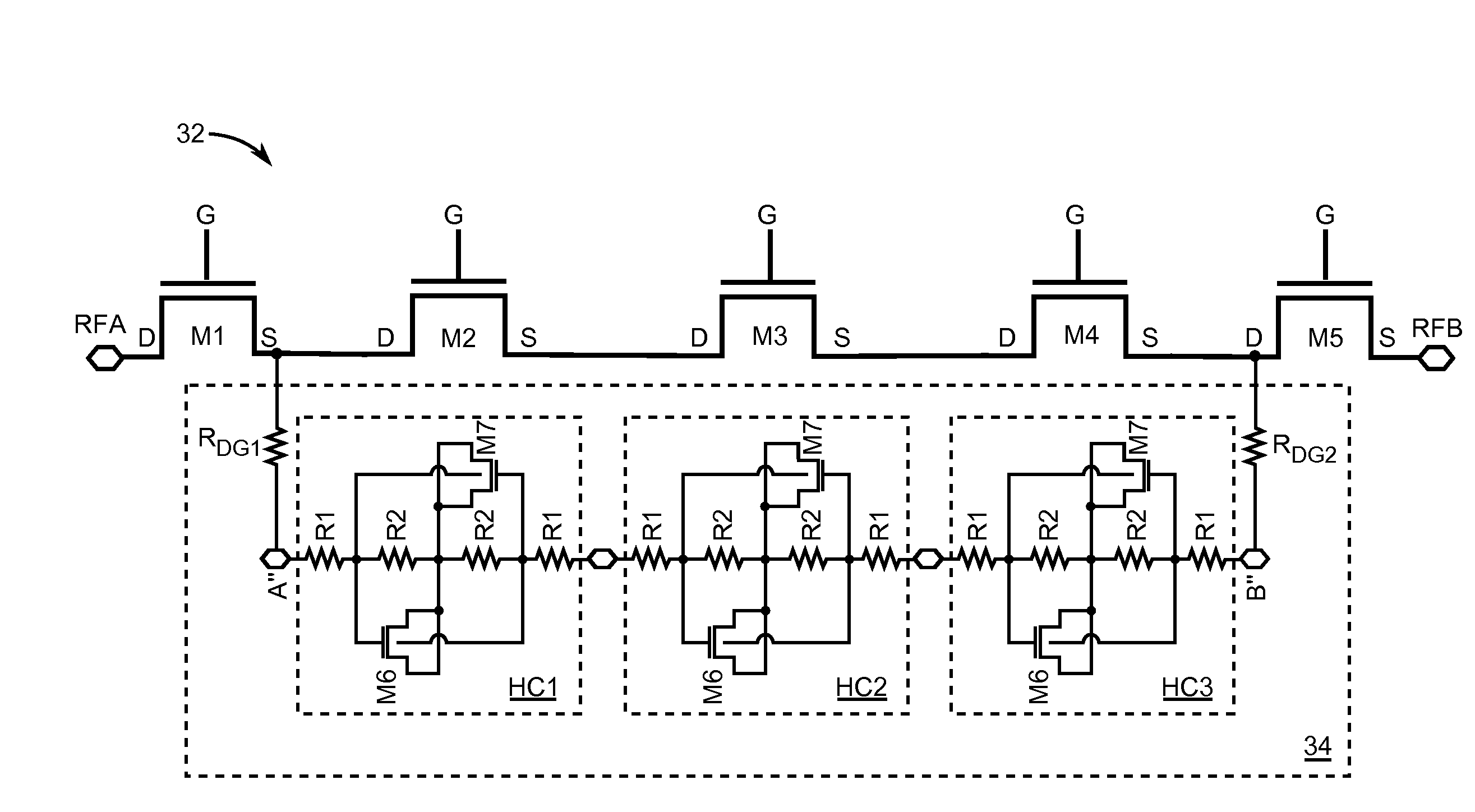
This patent is about a circuit that helps cancel out harmonic signals in an RF switch branch. It uses two transistors and two resistors to produce an inverse phase signal that reduces the harmonic signal. The circuit aims to improve the performance of the RF switch branch and ensure its stability.

Problems solved by technology

In non-contiguous inter-band operation where one of the receive bands is located at the H3 of the transmit frequency, the harmonics generated in a power amplifier (PA) and front end (FE) switches are not attenuated sufficiently enough to prevent receiver desensitization.
However, these related art methods such as adding static notch filters into the TX path may not be directly applicable to antenna tuning components.
The location of the RF switch relative to the antenna may make it difficult or impossible to implement diplexers, lowpass filters, notch filters, etc.

Method used


Image

  • Harmonic cancellation circuit for an RF switch branch
  • Harmonic cancellation circuit for an RF switch branch
  • Harmonic cancellation circuit for an RF switch branch

Examples


Embodiment Construction

[0023]The embodiments set forth below represent the necessary information to enable those skilled in the art to practice the disclosure and illustrate the best mode of practicing the disclosure. Upon reading the following description in light of the accompanying drawings, those skilled in the art will understand the concepts of the disclosure and will recognize applications of these concepts not particularly addressed herein. It should be understood that these concepts and applications fall within the scope of the disclosure and the accompanying claims.

[0024]Throughout the drawing figures, components such as resistors having identical labels / element numbers have substantially identical values.

[0025]Off-state switches are slightly nonlinear and produce harmonics. Circuits of the present disclosure add other harmonic generators such that a set of combined harmonics cancel out. The present disclosure provides circuits having structures designed to provide third harmonic (H3) generation...


PUM


Abstract

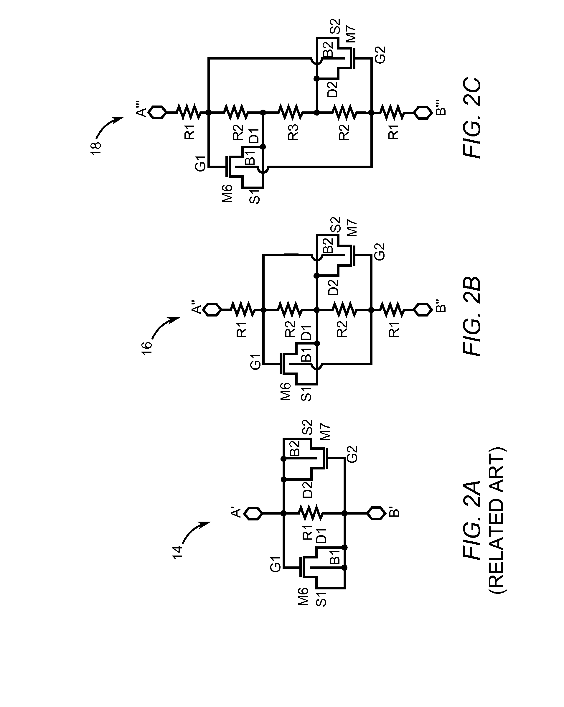
Disclosed is a harmonic cancellation circuit for an RF switch branch having a first transistor with a first gate terminal and a first body terminal, a second transistor having a second gate terminal coupled to the first body terminal, and having a second body terminal coupled to the first gate terminal. Also included is a first resistor coupled between a first coupling node and the second body terminal, and a second resistor coupled between a second coupling node and the first body terminal, wherein the first transistor and second transistor are adapted to generate an inverse phase third harmonic signal relative to a third harmonic signal generated by the RF switch branch, such that the inverse phase third harmonic signal is output through the first resistor and the second resistor to the RF switch branch to reduce the third harmonic signal.

Description

RELATED APPLICATIONS[0001]This application claims the benefit of U.S. provisional patent application No. 61 / 789,422, filed Mar. 15, 2013, the disclosure of which is incorporated herein by reference in its entirety.FIELD OF THE DISCLOSURE[0002]The present disclosure relates to suppressing third harmonic (H3) signals generated by electronic devices used in wireless communication products such as mobile terminals.BACKGROUND OF THE DISCLOSURE[0003]Demands for cellular downlink data are rapidly increasing as consumers use greater numbers of data intensive applications on their wireless data devices. This trend is encouraging wireless carriers and wireless service providers to explore new ways of increasing downlink data rates. One known method for increasing downlink data rates employs receive carrier aggregation. Receive carrier aggregation allows a wireless device to simultaneously receive data using multiple downlink frequency bands to improve throughput while simultaneously transmitt...

Claims


Application Information

Patent Timeline
IPC IPC(8): H03H11/04
CPCH03H11/0405H03H11/1213H01P1/15H03K17/102H03K17/687H03K17/693
Inventor KERR, DANIEL CHARLESBOLTON, ERIC K.PHELPS, ROBERT ANDREW
Owner QORVO US INC
Learn More