
Water Filtration Tower

a technology of water filtration tower and water filter, which is applied in water treatment multi-stage treatment, stationary filter element filter, water/sludge/sewage treatment, etc., and can solve problems such as high risk of endemic diarrheal diseases, poor, and poor people, and achieves the goal of never being achieved

Inactive Publication Date: 2014-09-18
AVYA GREEN TECH PVT LTD
View PDF11 Cites 2 Cited by
  • Summary
  • Abstract
  • Description
  • Claims
  • Application Information

AI Technical Summary

Benefits of technology

The patent text describes a water filtration device that can be used in developing countries to provide safe drinking water. The device uses a tube to create hydrostatic pressure to filter the water. The tube can be filled from the top or by a natural source, or through a pump. The device also includes a back-flow preventer to ensure the water flows in the correct direction. The device can be powered by a hand-pump or other locally available rotational torque generating device. The device can be used in various configurations to meet different needs. The technical effect of this invention is to provide a simple, effective solution for providing safe drinking water in developing countries where the need is greatest.

Problems solved by technology

The health consequences resulting from the inequity of poor services are sometimes considerable, as evidenced by the infant mortality rates which may vary between two and ten times in magnitude between those served with good water supplies and those which are not.
The poor, in particular, are at high risk from endemic diarrheal diseases, such as cholera.
However, given the enormous costs, engineering effort and political will required, this goal may never be achieved.
An interim solution is needed, and the need is dire.

Method used


Image

  • Water Filtration Tower
  • Water Filtration Tower
  • Water Filtration Tower

Examples


Embodiment Construction

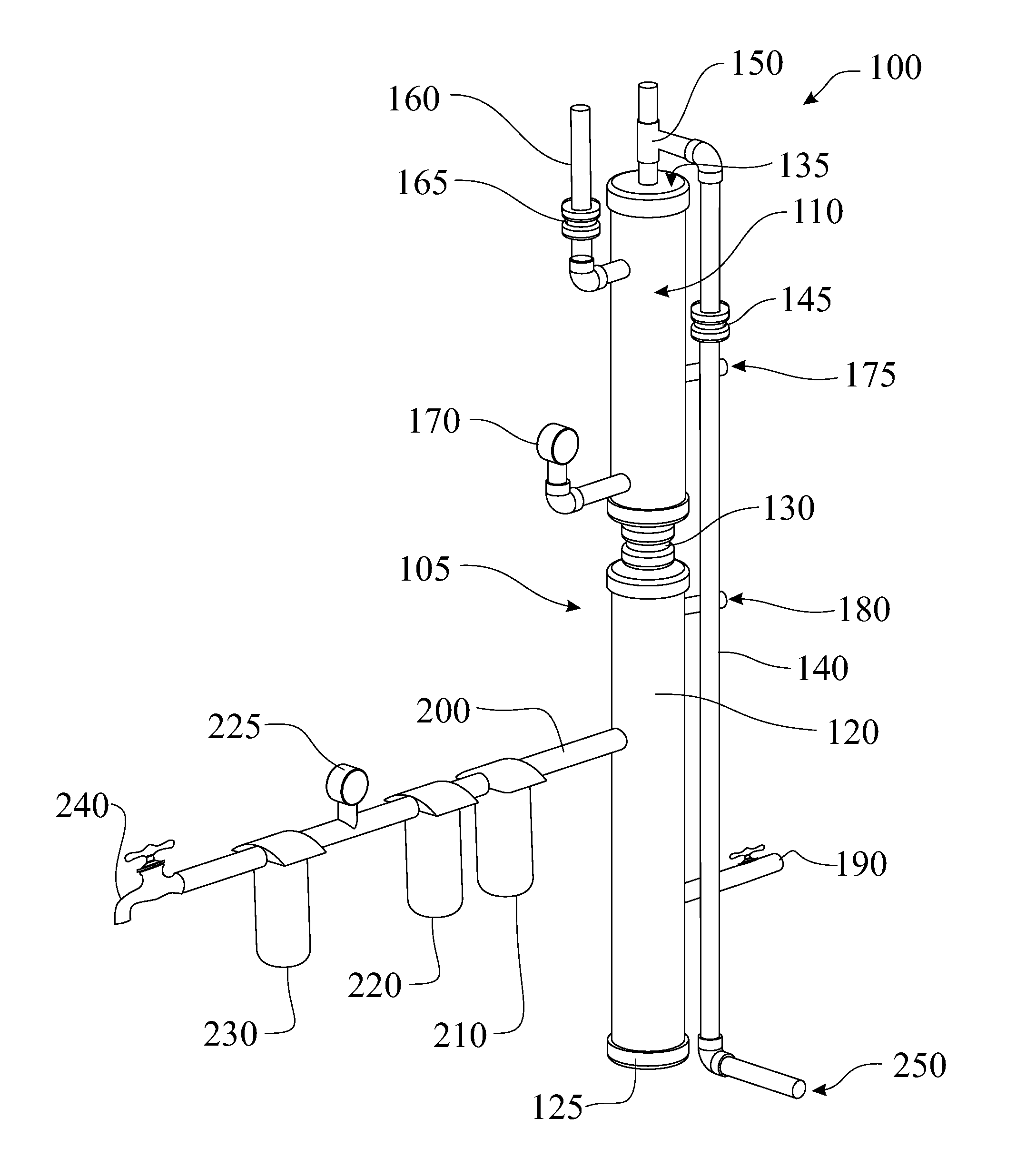
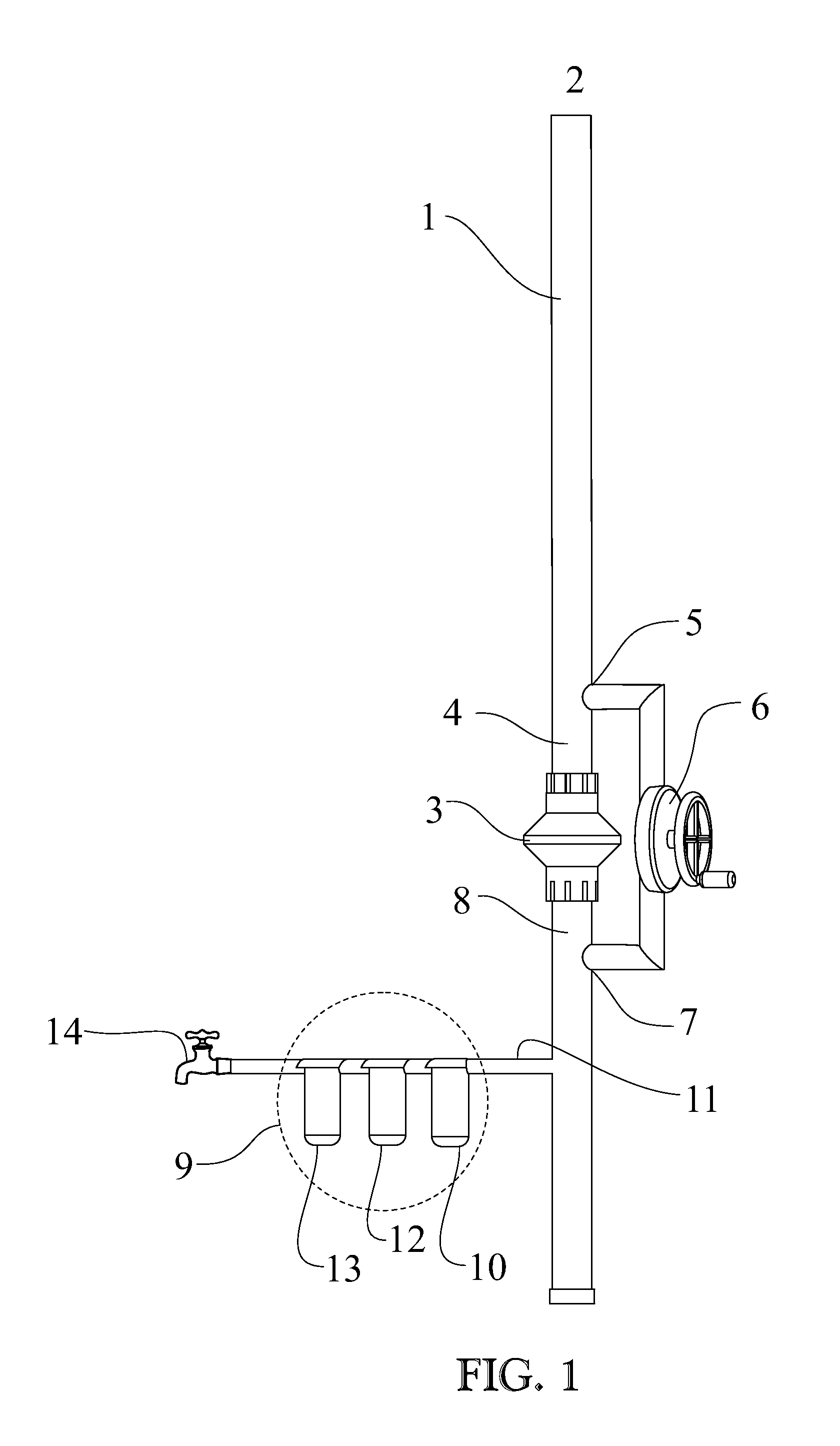
[0006]FIG. 1 shows and discloses a tube 1 containing water to develop hydrostatic pressure. The tube may be filled from the top 2 by a natural source located at a higher location than the terrain on which the device is installed, or by manual labor that may climb a hill or a building or a structure specifically designed and built for this purpose, or may be filled with a combination of pumps that may utilize renewable energy sources such as wind or solar. It may also be manually filled from roof tanks which collect rain water channeled from a roof to a collection container. The tube may be as high as a few feet to tens of feet depending on the specific requirements of the filtration or reverse osmosis media. The tube incorporates a back-flow preventer 3 which allows flow of water downward but not in the upward direction.

[0007]Just above the back-flow preventer, water from section 4 is directed to an outlet tube 5 which may be any size depending on local requirements and other parame...


PUM

PropertyMeasurementUnit
Pressureaaaaaaaaaa
Flow rateaaaaaaaaaa

Abstract

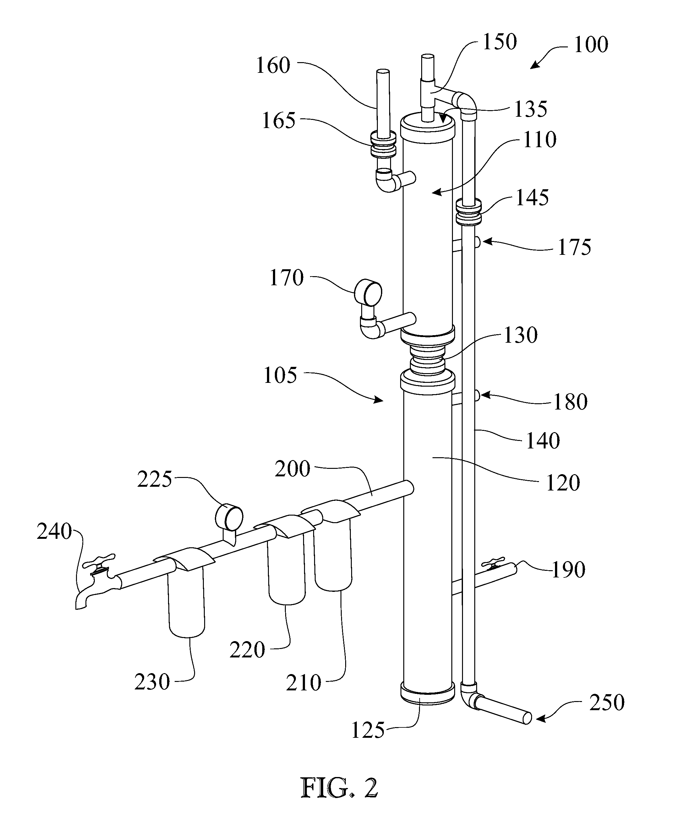
A village water filtration system includes a vertical tube which can be filled with non-potable water, attached to a human powered or other air pressurization source, the pressurized air forcing the flow of the water out of the tube and through a series of filters, producing potable water. The air pressurization source may be a common bicycle pump. The filtration media would be attached by a pipe proximal the lower chamber of the tube, whereas water and pressurized air would enter proximal the top of the tube. A series of check valves prevents the pressurized air and water from exiting anywhere except through the series of filters. Accessory ports for placing eater treatment chemicals may be provided. A clean out port is provided near the bottom of the vertical tube to remove sediment which may accumulate there. Advanced models may employ UV light, ozonation or other water cleaning devices and techniques.

Description

RELATED APPLICATIONS[0001]This utility patent claims priority from Provisional Patent Application Ser. No. 61 / 788,945 filed on Mar. 15, 2013 entitled “Water Filtration Tower” which is incorporated herein in its entirety.BACKGROUND OF THE INVENTION[0002]There is an ongoing commitment to alleviating the desperate condition of poor, under-served people, especially in the rural areas of the developing world by providing safe drinking water. United Nations reports show that more than a billion people worldwide are without potable water, and as a result, five million men, women, and children die from waterborne diseases every year. The World Health Organization's Water, Sanitation and Health branch wrote that an adequate supply of safe drinking water is universally recognized as a basic human need. The health consequences resulting from the inequity of poor services are sometimes considerable, as evidenced by the infant mortality rates which may vary between two and ten times in magnitude...

Claims


Application Information

Patent Timeline
IPC IPC(8): B01D29/56B01D29/60
CPCB01D29/56C02F1/001B01D29/606C02F1/004C02F1/32C02F1/441C02F1/50C02F1/52C02F1/78C02F3/00C02F5/00C02F2101/103C02F2201/005C02F2201/007C02F2201/009C02F2301/08Y02A20/212Y02A20/211
Inventor SISTLA, RAMANA VENKATA RAO
Owner AVYA GREEN TECH PVT LTD
Learn More