Puncture-free inner tube
- Summary
- Abstract
- Description
- Claims
- Application Information
AI Technical Summary
Benefits of technology
Problems solved by technology
Method used
Image

Examples
example 1
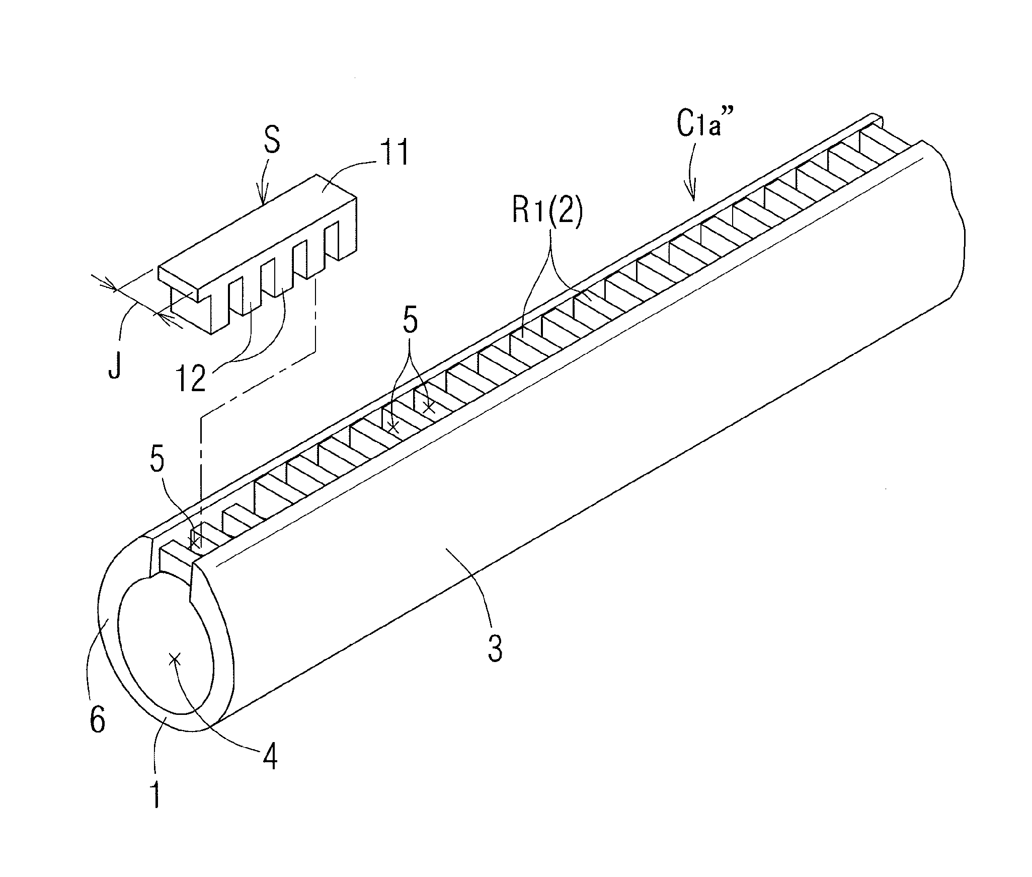
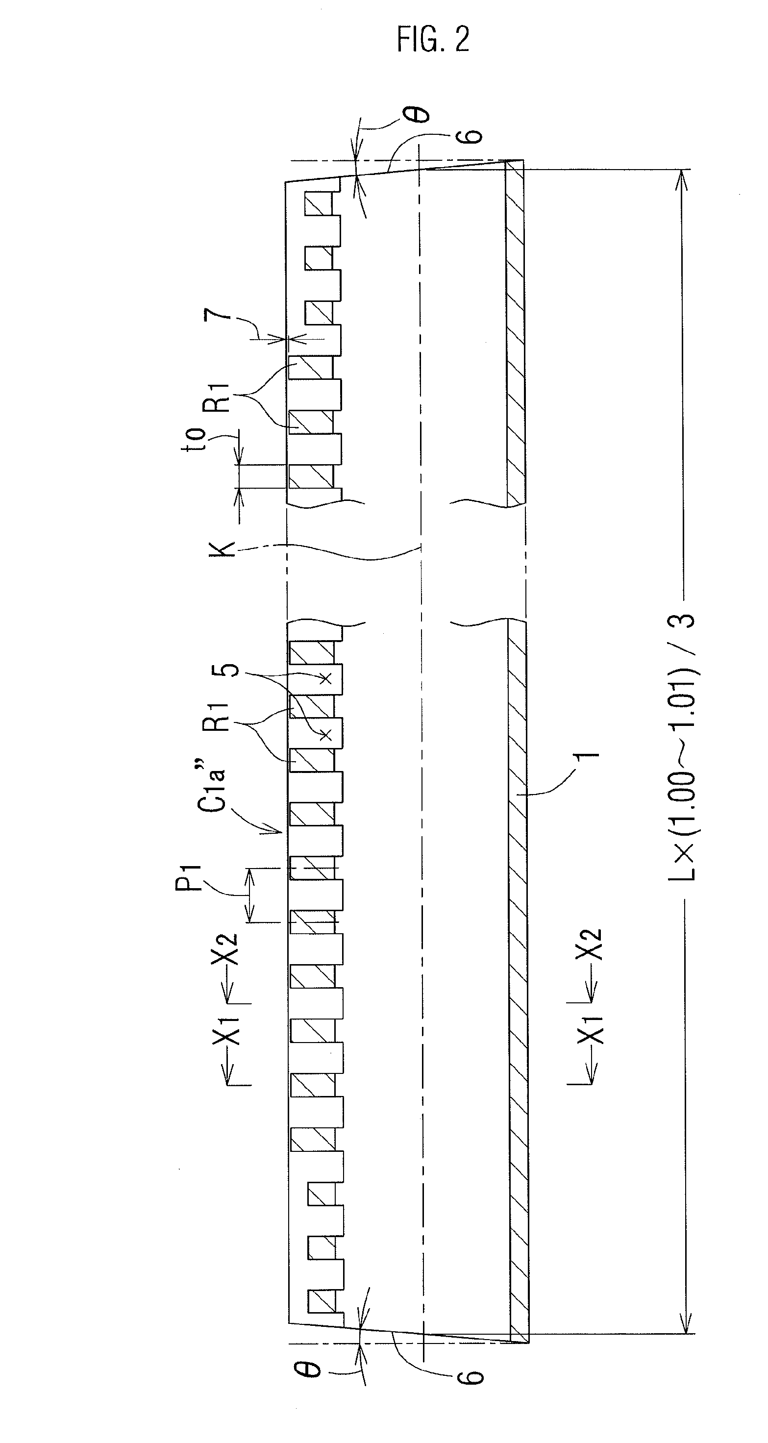
[0059]The invention will be described in more detail with reference to a specific example. A tube C1 according to the first embodiment of the invention will be described with reference to FIGS. 1 to 6. The tube C1 is constituted by three divided tubes C1a″ in a straight shape, and on inserting them in a tire T of a bicycle, the three divided tubes C1a″ in a straight shape are each bent into a circular arc shape corresponding to the diameter Dt of the tire T (i.e., the diameter of the part K, which is the center of the transversal cross section of an outer tire 51 shown in FIG. 6), and are connected to each other at end parts in the longitudinal direction thereof with a connecting members S, thereby forming into the tube C1 having an annular shape in total. The divided tube C1a″ in a straight shape has an irregular cylindrical shape having a hollow part 4 having a circular cross section having an inner diameter dc1 as shown in FIGS. 1 to 3, in which in the state where the divided tub...
example 2
[0084]A tube C2 of Example 2 will be described with reference to FIGS. 12 to 15. The tube C2 of Example 2 is largely different from the tube C1 of Example 1 only in the point that second ribs R2 are provided over between the ground part 1 and the side parts 3, and the reminder of the basic structure thereof is equivalent to the tube C1 of Example 1. Accordingly, the same parts are shown by the same symbols, the equivalent parts are shown by the same symbols with a prime (′), and only the different parts are described below. The transversal cross sectional shape of the divided tube C2a″ of the tube C2 is equivalent to the divided tube C1a″ in Example 1, and has an irregular cylindrical shape having a hollow part 4 having an inner diameter dc2 in transversal cross section, and circular arc grooves 8 are provided over between the ground part 1′ and the side parts 3′, in which the depth of the circular arc grooves 8 is gradually decreased from the ground part 1′ toward the side parts 3′...
example 3
[0091]A tube C3 of Example 3 will be described with reference to FIGS. 17 to 19. The tube C3 of Example 3 is different from the tube C2 of Example 2 in the point that the shape of the second ribs R2a′ and R2b′ formed on the outer circumferential surface of the ground part 1″ is different therefrom, and the reminder of the structure thereof is equivalent to the tube C2. Accordingly, the same parts are shown by the same symbols, and the second ribs R2′ as the sole difference are described below.
[0092]The second ribs R2a′ and R2b′, which are slanted forward and backward respectively, are formed on the outer circumferential surface of the ground part 1″ of the divided tube C3a″, and the second ribs R2a′ and R2b′ intersect with each other at the bottom position of the ground part 1″, which is demanded to have the largest strength against the ground pressure, thereby providing a desirable structure for ensuring the strength of the tube C3. The tube C3 is reduced in weight by providing the...
PUM
 Abstract
Description
Claims
Application Information
 - R&D
- Intellectual Property
- Life Sciences
- Materials
- Tech Scout
- Unparalleled Data Quality
- Higher Quality Content
- 60% Fewer Hallucinations
Browse by: Latest US Patents, China's latest patents, Technical Efficacy Thesaurus, Application Domain, Technology Topic, Popular Technical Reports.
© 2025 PatSnap. All rights reserved.Legal|Privacy policy|Modern Slavery Act Transparency Statement|Sitemap|About US| Contact US: help@patsnap.com