Heat exchanger, heat recovery ventilator including the same, and method for defrosting and checking operations thereof

a heat exchanger and heat recovery technology, applied in the field of heat exchangers and heat recovery ventilators, can solve the problems of two-way multi-flow heat exchangers, high manufacturing costs, and the use of expensive metallic materials such as aluminum, and achieves a low manufacturing cost, simple manufacturing process, and reduced the number of factors which cause troubl

Inactive Publication Date: 2014-09-18
DONG YANG E & E CO LTD
View PDF36 Cites 21 Cited by
  • Summary
  • Abstract
  • Description
  • Claims
  • Application Information

AI Technical Summary

Benefits of technology

The present invention provides a heat exchanger with a simple manufacturing process and low manufacturing cost because no expensive materials such as aluminum are used. The heat exchanger has a multi-flow-path structure and a single-flow-path structure, reducing the ratio of ice formation area and unavailable heat exchange area. The heat exchanger does not accumulate dust and solves the problem of contaminated flow paths and decreased ventilation efficiency. The ice formation state of the heat recovery ventilator can be detected without using an expensive pressure sensor, and the heat recovery ventilator can accurately determine the ice formation state by complementing the conventional method in which the temperature sensor is used to detect only the temperature of outdoor air or the temperature of return air or supplied.

Problems solved by technology

The two-way multi-flow-path heat exchanger has a disadvantage in that it is manufactured through a complex manufacturing process.
The two-way single-flow-path heat exchanger of FIG. 3 may be manufactured through a simple process, but has a disadvantage in that expensive metallic material such as aluminum must be used.
However, since the amount of exhaust air is larger than the amount of supplied air, outdoor air is supplied to the interior through interior gaps.
Thus, although the ventilation efficiency is not considerably degraded, the entire heat exchange efficiency is further degraded because there exists the air which is supplied to the interior without passing through the heat recovery ventilator.
Then, since the exhaust air cannot pass through the frozen part, the heat exchange surface corresponding to the frozen part may lose the function thereof.
However, since additional electric energy is needed, this method is not effective.
In this case, the frozen water may block the supplied air flow path of the heat exchanger.
Furthermore, when this method is used in a place where indoor air is significantly contaminated by dust or the like, the supplied air flow path may be contaminated.
However, since ventilation is stopped during the defrosting operation, the ventilation efficiency may be degraded, and the supplied air flow path may be frozen or contaminated.
Thus, when an ice formation state is determined only through the outdoor air temperature, an unnecessary defrosting operation may be performed, or the defrosting operation may be performed after a considerable amount of ice is formed.
This method requires expensive pressure sensors, and the temperature ratio of two temperature sensors is changed according to the outdoor temperature at the same heat exchange efficiency, and changed according to the heat exchange efficiency of the heat exchanger at the same outdoor temperature.

Method used


Image

  • Heat exchanger, heat recovery ventilator including the same, and method for defrosting and checking operations thereof
  • Heat exchanger, heat recovery ventilator including the same, and method for defrosting and checking operations thereof
  • Heat exchanger, heat recovery ventilator including the same, and method for defrosting and checking operations thereof

Examples


third embodiment

[0091]FIG. 15 illustrates a heat recovery ventilator which performs a defrosting operation using the double heat exchanger 90 according to the present invention (refer to FIG. 13). The heat recovery ventilator performs a defrosting operation in the same method as illustrated in FIG. 14.

[0092]The defrosting method of FIGS. 14 and 15 is a negative pressure-type defrosting method which does not supply outdoor air to the interior but discharge outdoor air to the exterior during a defrosting operation. Thus, although the ventilation efficiency is not degraded like the method of FIG. 6, a problem may occur when the defrosting method is used in a place where outdoor air is introduced into the interior through a contaminated path such as an outlet of a kitchen hood.

[0093]FIG. 16 illustrates that a connection path (second connection path) for connecting the exhaust air outlet (that is, exhaust air discharge chamber) to the interior is installed and a flow path selection damper 105 (second fl...

first embodiment

[0102]In the method according to the present invention, three temperature sensors are used to perform a defrosting operation, a normal operation, and a checking operation as illustrated in FIG. 18.

[0103]FIG. 18 illustrates a method in which a return air temperature sensor, an outdoor air temperature sensor, and a supplied air temperature sensor are installed in the return air introduction chamber, the outdoor air introduction chamber, and the supplied air discharge chamber, respectively, and a defrosting operation, a normal operation, and a checking operation are performed on the basis of a result obtained by calculating the temperature exchange efficiency η using temperatures detected through the respective temperature sensors in a normal operation state.

[0104]When the temperature exchange efficiency η becomes equal to or less than reference efficiency ηS, the heat recovery ventilator determines that flow path blockage occurred in the exhaust air stream. When the temperature exchan...


PUM

PropertyMeasurementUnit
Angleaaaaaaaaaa

Abstract

The present invention relates to a heat exchanger, a method for manufacturing the same, a heat recovery ventilator (HRV) including the same, and a method for defrosting and checking operations thereof.

Description

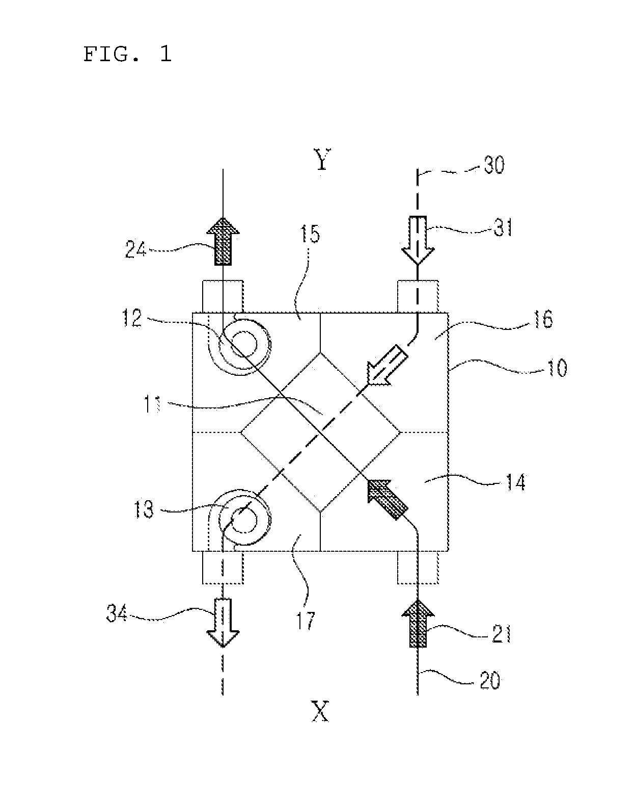
RELATED APPLICATION[0001]This application claims the benefit of priority of Korean Patent Application No. 10-2013-0027412 filed Mar. 14, 2013, the contents of which are incorporated herein by reference in their entirety.TECHNICAL FIELD[0002]The present invention relates to a heat exchanger, a method for manufacturing the same, a heat recovery ventilator (HRV) including the same, and a method for defrosting and checking operations thereof.BACKGROUND ART[0003]FIG. 1 illustrates a general heat recovery ventilator (HRV) 10. The heat recovery ventilator 10 includes a heat exchanger 11, a supplied air fan 12, an exhaust air fan 13, an outdoor air introduction chamber 14, a supplied air discharge chamber 15, a return air introduction chamber 16, and an exhaust air discharge chamber 17. The heat exchanger 11 performs heat exchange between supplied air stream 20 supplied to the interior Y from the exterior X and exhaust air stream 30 discharged from the interior Y to the exterior X.[0004]The...

Claims


Application Information

Patent Timeline
IPC IPC(8): F28F1/00F25D21/00F24F12/00B23P15/26
CPCF28F1/00B23P15/26F28F2255/16F24F12/006F25D21/006F28D9/0031F28D9/0062F28D9/0081F28F3/025F24F11/41Y02B30/56Y10T29/4935F24F7/08F28F3/00F28F9/00
Inventor JUNG, IN SOOK
Owner DONG YANG E & E CO LTD
Why Eureka
Try Eureka