Eureka AIR delivers breakthrough ideas for toughest innovation challenges, trusted by R&D personnel around the world.

Power tool assembly, power tool, and auxiliary handle member

a technology of auxiliary handle and power tool, which is applied in the direction of manufacturing tools, portable power-driven tools, drilling machines, etc., can solve the problems of auxiliary handle falling off from the housing of the power tool, difficult to properly use the power tool in a small space, and difficulty in gaining sufficient leverage to properly operate the power tool, etc., to achieve the effect of increasing the longitudinal length of the housing

Inactive Publication Date: 2014-09-11
MAKITA CORP
View PDF23 Cites 28 Cited by
  • Summary
  • Abstract
  • Description
  • Claims
  • Application Information

AI Technical Summary

Benefits of technology

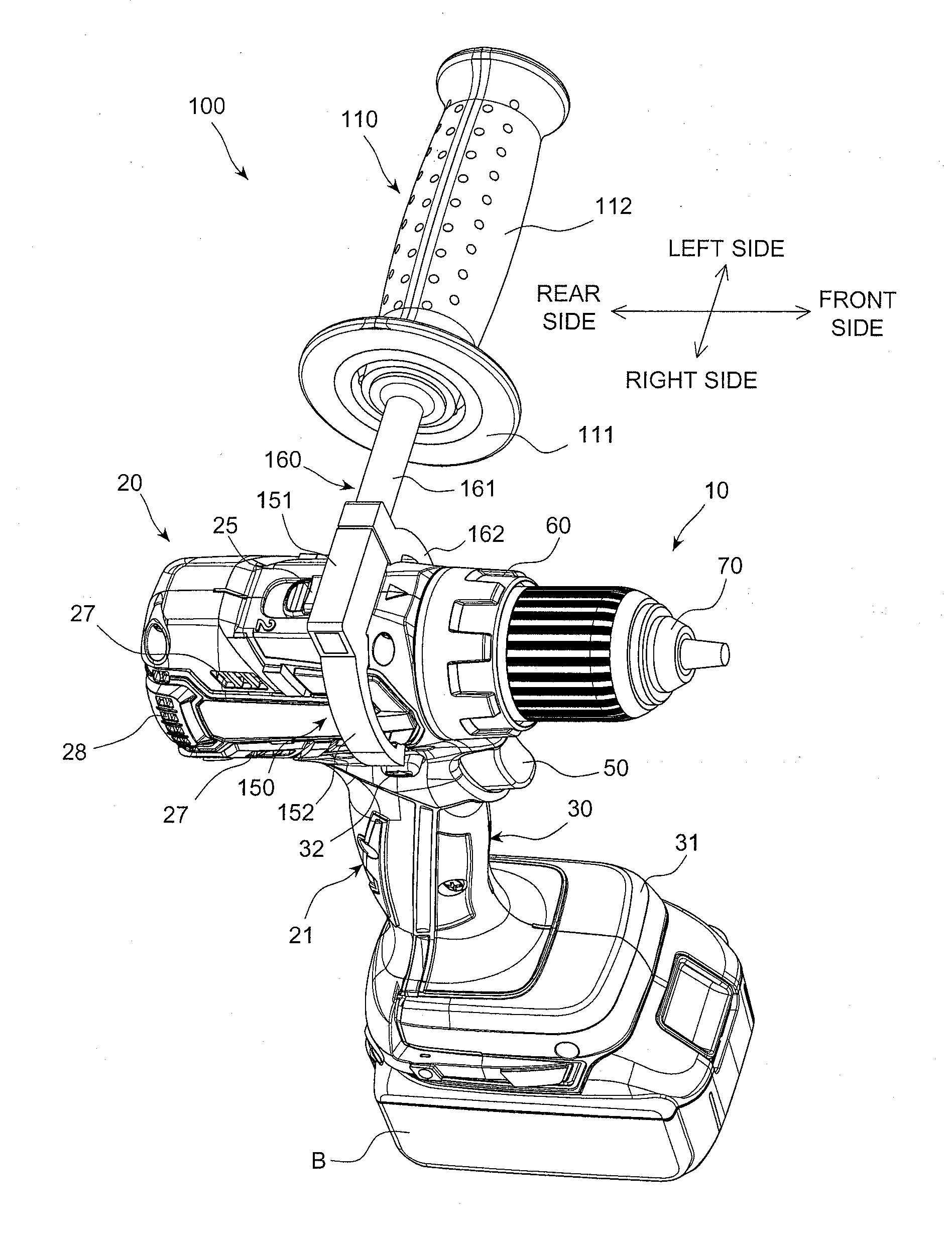
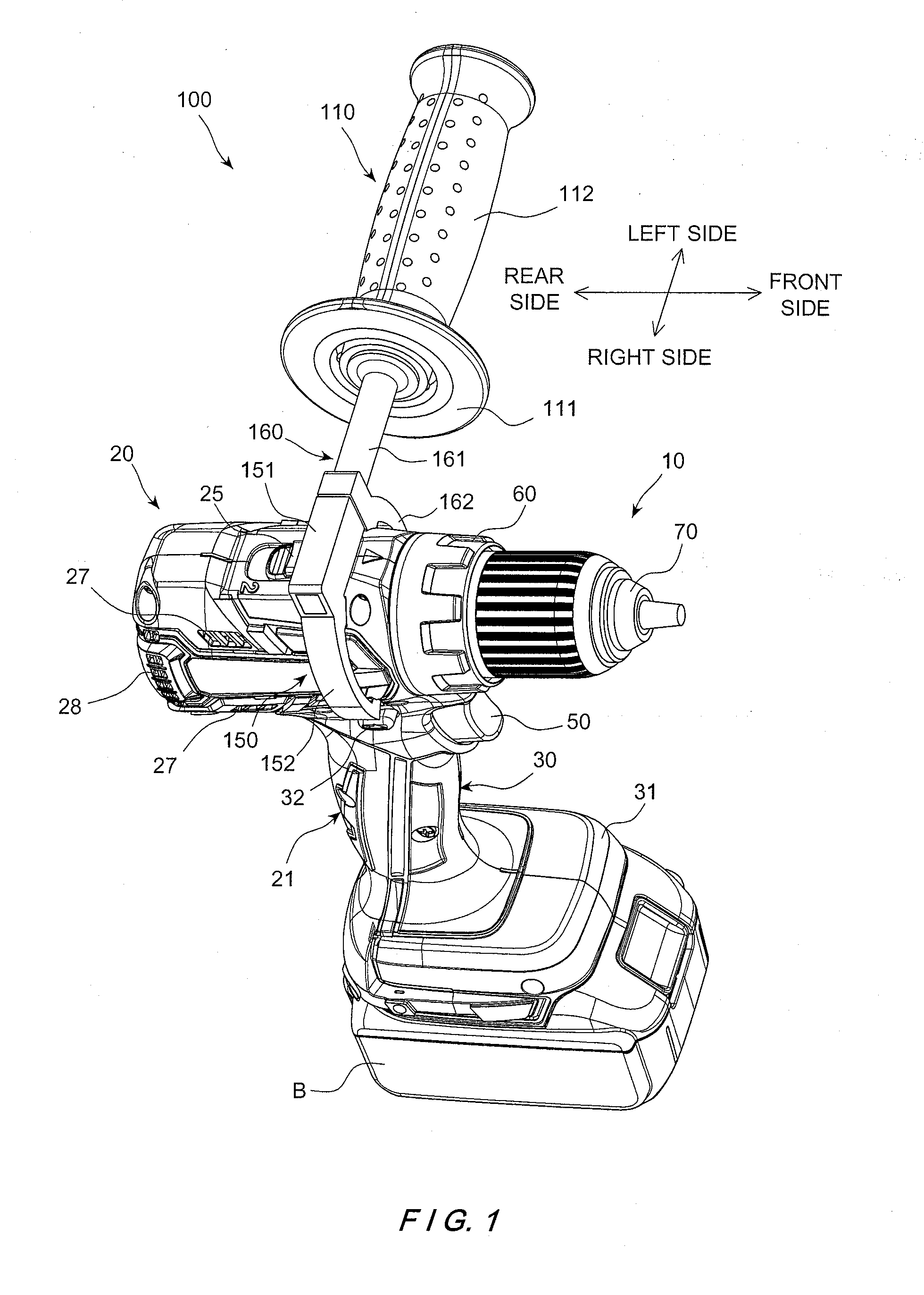
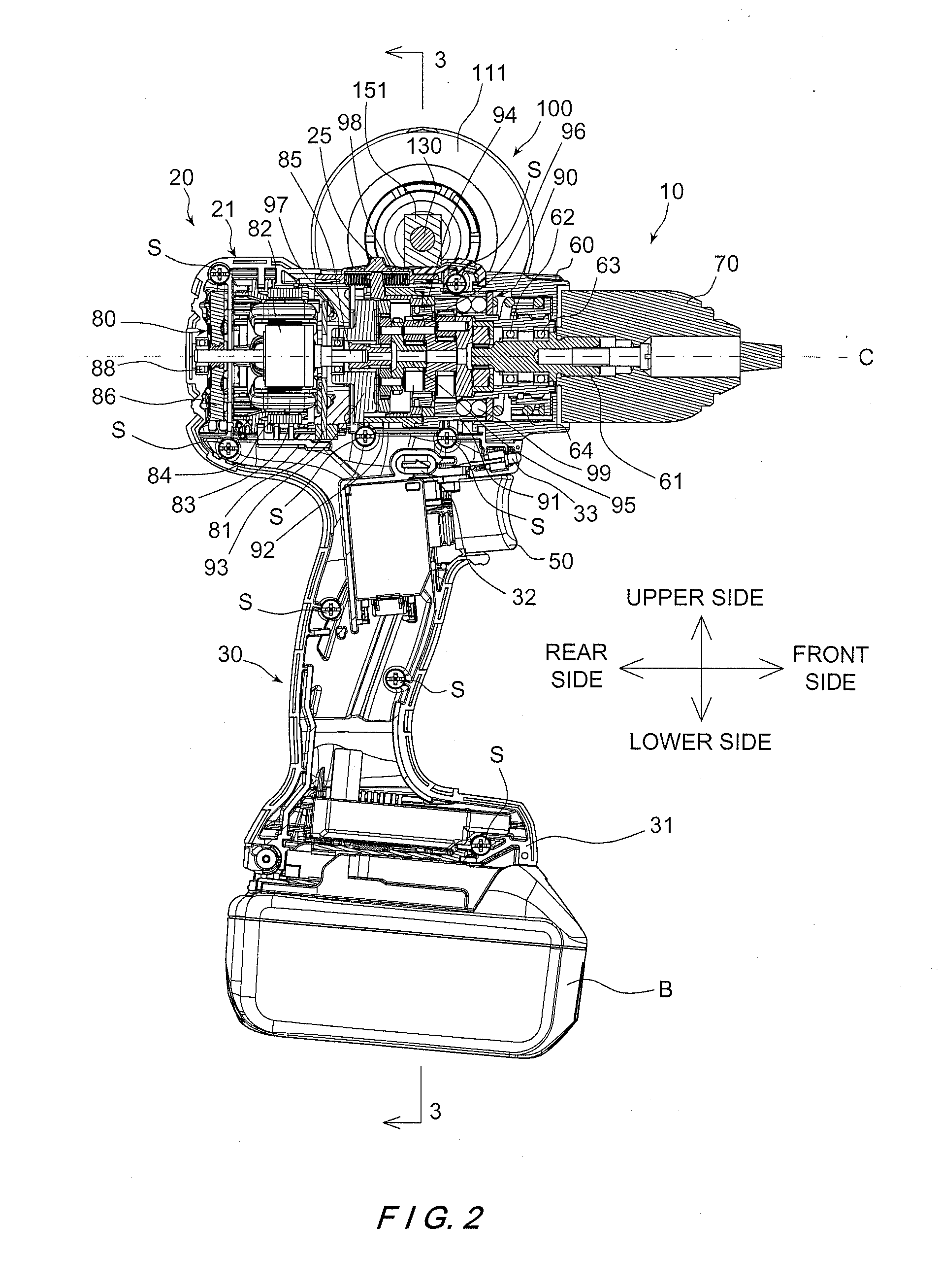
The patent text describes a power tool assembly with an auxiliary handle member. The auxiliary handle member is fixed to the power tool's housing and includes a first arm part and a second arm part that can move relative to each other to change the distance between them. This allows for secure attachment of the auxiliary handle to the power tool and ensures that it remains fixed when the power tool is used in a confined space. The auxiliary handle member can be easily manufactured without adding weight or cost to the power tool. The technical effects of this design include improved attachment of the auxiliary handle to the power tool, increased reliability, and reduced space requirements.

Problems solved by technology

However, it is sometimes difficult to gain sufficient leverage to properly operate the power tool by holding the power tool with only one hand.
However, when the longitudinal length of the power tool is large, it becomes difficult to use the power tool in a small, confined space.
Moreover, since the semi-clamps and the housing are held together only by the frictional force, when large torque is imparted on the power tool during operation, the auxiliary handle may accidentally slip off from the housing of the power tool or become misaligned with respect to the housing.
On the other hand, in the second example of the conventional auxiliary handle as described above, since the first clamp and the second clamp are arranged to together surround only about a 90 degree portion of a chuck of the power tool, attachment between the auxiliary handle and the power tool may be unreliable.
In such a case too, when large torque is imparted on the power tool during operation, the auxiliary handle may accidentally slip off from the housing of the power tool.
Moreover, when the apertures for engaging the first and second clamps are provided in a ring member, the ring member needs to be made of material having high rigidity and stiffness, such as metal, which would increase weight and manufacturing cost of the power tool.
On the other hand, when the power tool is provided with a bulged part in which the apertures are formed, the bulged part bulges out from a main body of the power tool even though the bulged part has no use when the power tool is used without the auxiliary handle.

Method used


Image

  • Power tool assembly, power tool, and auxiliary handle member
  • Power tool assembly, power tool, and auxiliary handle member
  • Power tool assembly, power tool, and auxiliary handle member

Examples


second embodiment

[0065]Referring now to FIGS. 8-11, a power tool assembly including the power tool 10 and an auxiliary handle member 200 in accordance with a second embodiment will now be explained. In view of the similarity between the first and second embodiments, the parts of the second embodiment that are identical to the parts of the first embodiment will be given the same reference numerals as the parts of the first embodiment. Moreover, the descriptions of the parts of the second embodiment that are identical to the parts of the first embodiment may be omitted for the sake of brevity.

[0066]The power tool assembly according to the second embodiment differs from the first embodiment in the structure of the auxiliary handle member 200. In other words, in the second embodiment, the auxiliary handle member 200 is selectively coupled to the power tool 10 to provide a secondary grip position for a user to support the power tool 10 with both hands during operation.

[0067]Referring now to FIGS. 8 and 9...

third embodiment

[0082]Referring now to FIGS. 12-15, a power tool assembly including the power tool 10 and an auxiliary handle member 300 in accordance with a third embodiment will now be explained. In view of the similarity between the first, second and third embodiments, the parts of the third embodiment that are identical to the parts of the first or second embodiment will be given the same reference numerals as the parts of the first or second embodiment. Moreover, the descriptions of the parts of the third embodiment that are identical to the parts of the first or second embodiment may be omitted for the sake of brevity.

[0083]The power tool assembly according to the third embodiment differs from the first embodiment in the structure of the auxiliary handle member 300. In other words, in the second embodiment, the auxiliary handle member 300 is selectively coupled to the power tool 10 to provide a secondary grip position for a user to support the power tool 10 with both hands during operation.

[0...

fourth embodiment

[0105]Referring now to FIGS. 16-26, a power tool assembly including the power tool 10′ and an auxiliary handle member 400 in accordance with a fourth embodiment will now be explained. In view of the similarity between the first and fourth embodiments, the parts of the fourth embodiment that are identical to the parts of the first embodiment will be given the same reference numerals as the parts of the first embodiment. Moreover, the descriptions of the parts of the fourth embodiment that are identical to the parts of the first embodiment may be omitted for the sake of brevity. The parts of the fourth embodiment that differ from the parts of the first embodiment will be indicated with a single prime (′).

[0106]In the fourth embodiment, the power tool 10′ is a cordless driver drill. The power tool 10′ differs from the power tool 10 illustrated in the first embodiment except for the auxiliary handle member mounting structure provided in the power tool 10′. More specifically, as shown in...


PUM

PropertyMeasurementUnit
circumferenceaaaaaaaaaa
distanceaaaaaaaaaa
frictional forcesaaaaaaaaaa

Abstract

A power tool assembly includes a power tool and an auxiliary handle member. An outer surface of a main body portion of the power tool includes first and second engagement structures. A fixing portion of the auxiliary handle member is fixed to the main body portion of the power tool with the fixing portion surrounding more than 180 degree of a circumference of the main body portion when viewed along a longitudinal axis of the main body portion. The fixing portion includes a first arm part with a first engagement section engaging with the first engagement structure and a second arm part with a second engagement section engaging with the second engagement structure. The first arm part and the second arm part are movable relative to each other to change a distance between the first engagement section and the second engagement section.

Description

BACKGROUND[0001]1. Field of the Invention[0002]The present invention generally relates to a power tool assembly. More specifically, the present invention relates to a power tool assembly in which an auxiliary handle member is removably coupled to a power tool.[0003]2. Background Information[0004]A conventional power tool, such as a driver drill, a hammer drill, an impact driver drill and the like, often includes a pistol-shaped housing having a grip portion, which is usually grasped by a user with one hand during operation. However, it is sometimes difficult to gain sufficient leverage to properly operate the power tool by holding the power tool with only one hand. Therefore, it is well known to provide an auxiliary handle or side handle on the power tool to enable the user to support the power tool with both hands during operation.[0005]One example of a conventional side handle for a hand-held device includes a pair of semi-clamps coupled to a hand grip of the side handle. Each of ...

Claims


Application Information

Patent Timeline
Patent Type & Authority Applications(United States)
IPC IPC(8): B25F5/02B23Q9/00
CPCB23Q9/00B25F5/02B25F5/026
Inventor KONDO, TOMOYUKI
Owner MAKITA CORP
Why Eureka
Eureka Blog
Learn More