Hydraulically controlled rotary harrow for tillage apparatus and system
a rotary harrow and rotary harrow technology, applied in soil-working methods, agricultural machines, agricultural tools and machines, etc., can solve problems such as significant problems and damage, harrows to twist against mountings, and reduce the likelihood of getting stuck in wet soil conditions
- Summary
- Abstract
- Description
- Claims
- Application Information
AI Technical Summary
Benefits of technology
Problems solved by technology
Method used
Image
Examples
first embodiment
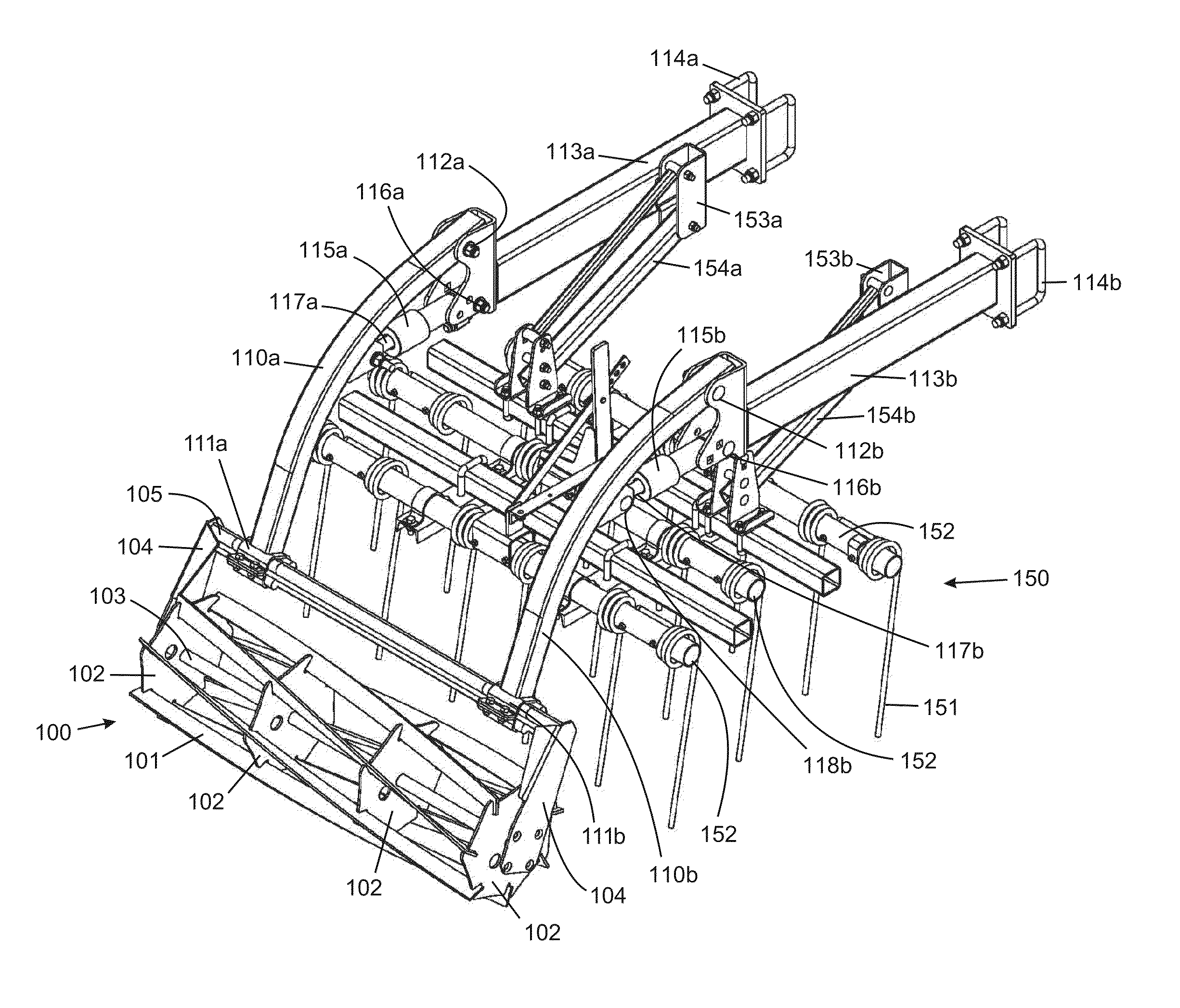
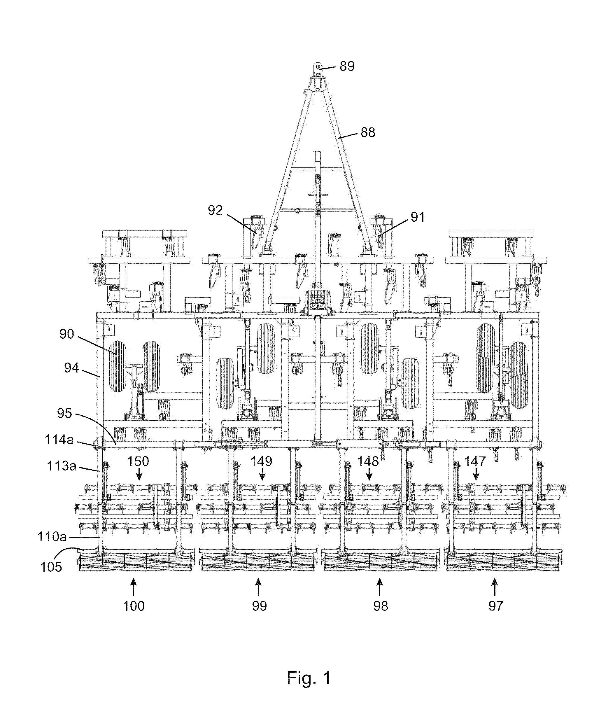
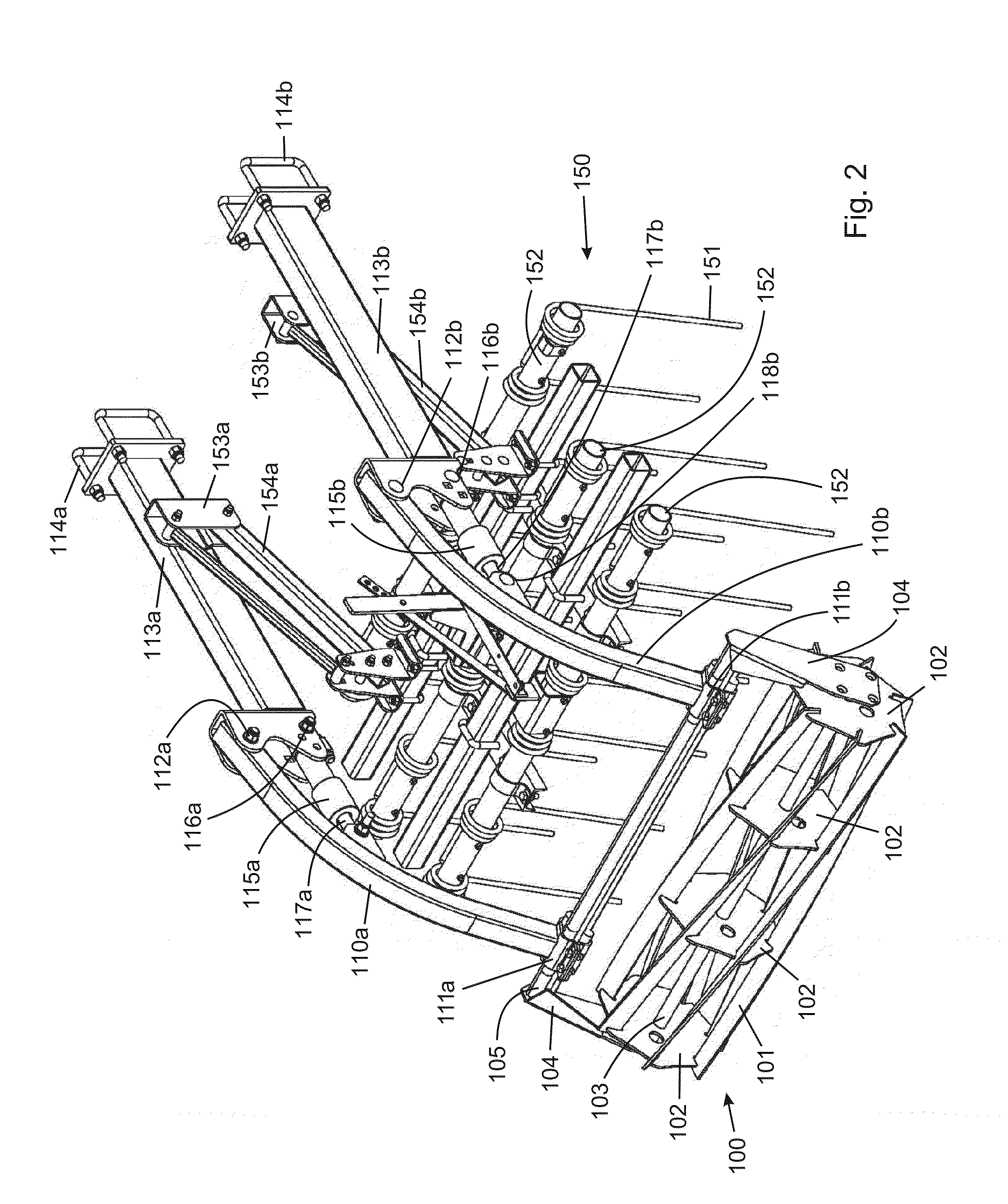
[0085]FIG. 12A is a schematic diagram of a hydraulic circuit for use in controlling a gang of four transversely spaced apart rotary harrows. The circuit comprises a plurality of hydraulic lines containing hydraulic fluid for transmitting hydraulic pressure to eight double acting hydraulic cylinders 550a-h. Cylinders 550a,550b control two mounting arms for a first rotary harrow, cylinders 550c,550d control two mounting arms for a second rotary harrow, cylinders 550e,550f control two mounting arms for a third rotary harrow and cylinders 550g,550h control two mounting arms for a fourth rotary harrow. The cylinders are shown retracted, meaning that the harrow is engaged with the ground. Various couplings, including two-way couplings (e.g. 510) and three-way couplings (e.g. 512) join lines to provide fluid pressure to various parts of the circuit. One or more of the couplings may contain shut-off valves if desired.
[0086]Under normal operation in which the hydraulic cylinders are retracte...
second embodiment
[0089]FIG. 12B is a schematic diagram of a hydraulic circuit that is similar to the circuit of FIG. 12A except that two additional relief valves 644,645 are placed in the circuit on opposite sides. Left side relief valve 644 is proximal hydraulic cylinders 650a-d and right side relief valve 645 is proximal hydraulic cylinders 650e-h. The left and right side relief valves are set to open at a set pressure that is the same as the set pressure of relief valve 604 in double function valve 600 (although the set pressure of one or more of the relief valves could be different that the others if desired). When a rotary harrow on the left side strikes a rock and pressure in one or more of cylinders 650a-d increases beyond the set pressure of relief valve 644, the valve will open to relieve the pressure as described above and excess fluid will flow into line 631 and through four-way coupling 632, and can ultimately flow to the other side of cylinders 650a-d or through line 633 and eventually ...
third embodiment
[0090]FIG. 12C is a schematic diagram of a hydraulic circuit that is similar to the circuit of FIG. 12A except that two hydraulic accumulators 744,745 are placed in the circuit on opposite sides. The accumulators occupy the same positions in the circuit as the two additional relief valves do in FIG. 12B. Hydraulic accumulators are simply hydraulic empty loops of hydraulic line into which excess hydraulic fluid can be pushed when the pressure in the cylinders increases due to the harrow striking a rock. They serve a similar function as the additional relief valves in FIG. 12B, but the advantage of accumulators over additional relief valve lies in the elimination of the extra lines and couplings associated with the additional relief valves. However, hydraulic accumulators have a limit to the amount of pressure that can be relieved.
PUM
 Abstract
Description
Claims
Application Information
 - R&D
- Intellectual Property
- Life Sciences
- Materials
- Tech Scout
- Unparalleled Data Quality
- Higher Quality Content
- 60% Fewer Hallucinations
Browse by: Latest US Patents, China's latest patents, Technical Efficacy Thesaurus, Application Domain, Technology Topic, Popular Technical Reports.
© 2025 PatSnap. All rights reserved.Legal|Privacy policy|Modern Slavery Act Transparency Statement|Sitemap|About US| Contact US: help@patsnap.com


