Laser machining apparatus
a technology of laser machining and machining steps, which is applied in the direction of mechanical equipment, manufacturing tools, turbines, etc., can solve the problems of inefficiency of high-quality laser machining processes and increase the number of laser machining steps, so as to reduce the number of machining failures, shorten the time required, and reduce the effect of machining failures
- Summary
- Abstract
- Description
- Claims
- Application Information
AI Technical Summary
Benefits of technology
Problems solved by technology
Method used
Image
Examples
first embodiment
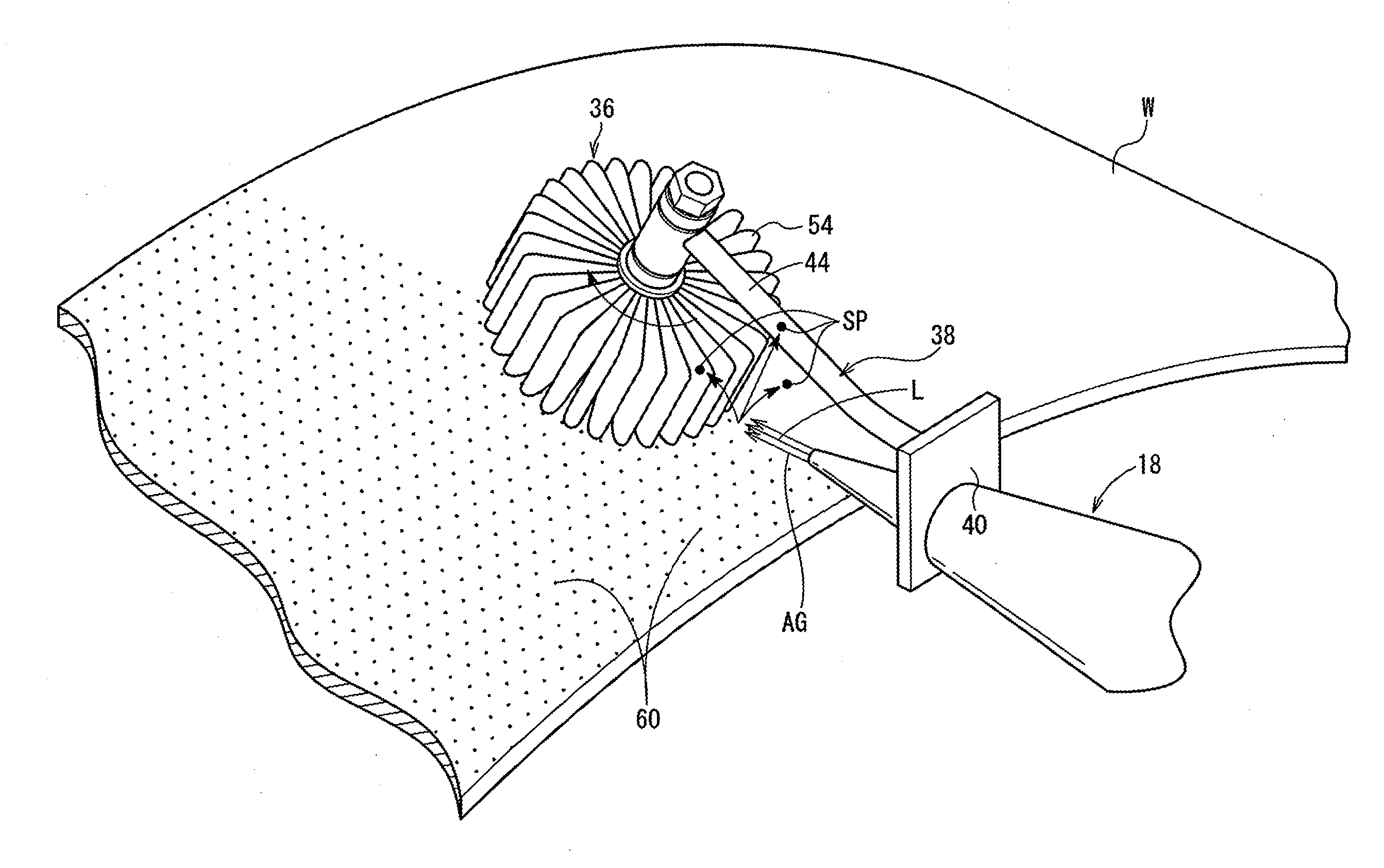
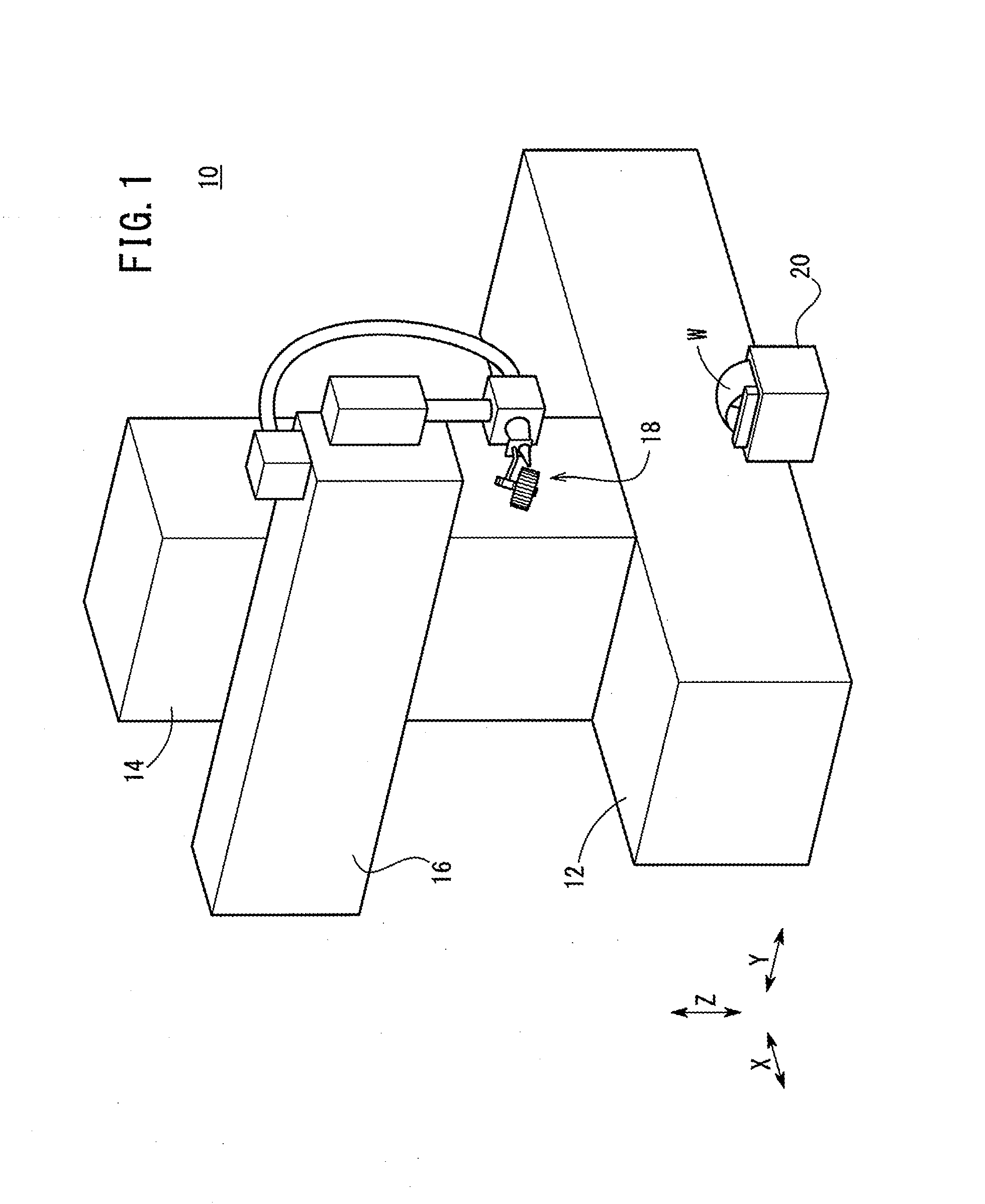
[0026]As shown in FIG. 1, a laser machining apparatus 10 according to the present invention has a base 12 extending along an X-axis direction, i.e., along left and right directions. The base 12 supports thereon an X-axis table 14 movable along the X-axis direction, and the X-axis table 14 supports thereon a Y-axis table 16 movable along a Y-axis direction, i.e., along forward and rearward directions perpendicular to the X-axis direction.
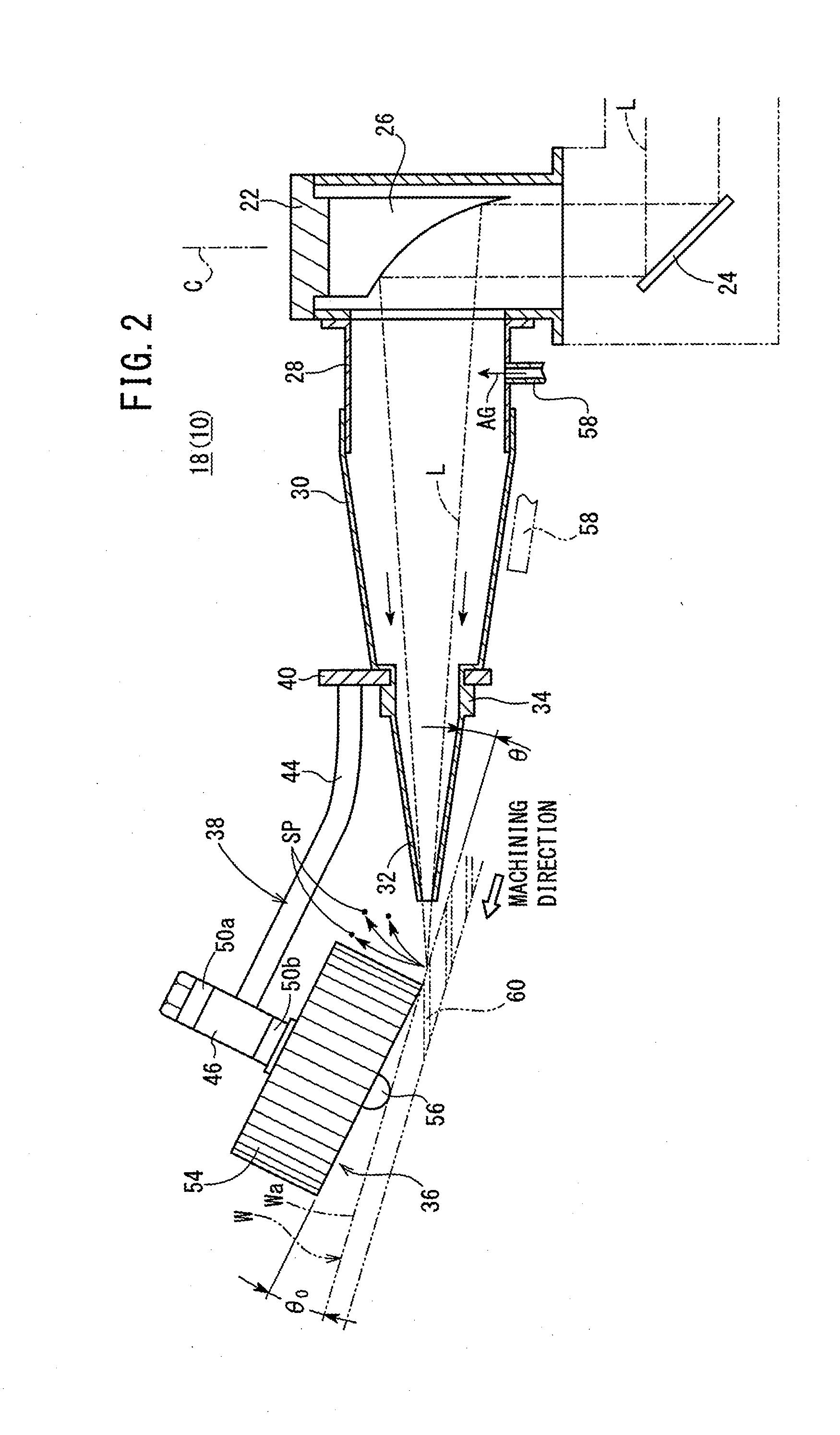
[0027]The laser machining apparatus 10 also includes a machining head 18 mounted on the Y-axis table 16 for movement along a Z-axis direction, i.e., upward and downward directions perpendicular to the X-axis direction and the Y-axis direction. The machining head 18 is movable about two axes, i.e., rotatable about a C-axis and tiltable about an A-axis.
[0028]Consequently, the laser machining apparatus 10 is a five-axis laser machining apparatus operable along the X-axis, the Y-axis, and the Z-axis, as well as about the C-axis and the A-axis. However, t...
second embodiment
[0053]As shown in FIGS. 5 and 6, a laser machining apparatus 61 according to the present invention includes a machining head 62. The machining head 62 includes the housing 22, which houses reflecting mirrors 24 therein, and the sleeve 28, which houses a machining lens 26a that serves as a light collecting optical system.
[0054]Components of the laser machining apparatus 61 according to the second embodiment, which are identical to those of the laser machining apparatus 10 according to the first embodiment, are denoted by identical reference characters, and such features will not be described in detail below. The same holds true for a laser machining apparatus according to a third embodiment of the present invention, to be described later.
[0055]The machining head 62 includes a laser nozzle 30a and a nozzle tip 32a, which is mounted on the laser nozzle 30a. The laser nozzle 30a has an internally threaded hole 64a defined by an inner circumferential surface of a distal end of the laser ...
third embodiment
[0058]As shown in FIGS. 7 and 8, a laser machining apparatus 70 according to the present invention includes a sputter blocking jig 74, which is mounted on the distal end of a machining head 18 by a joint 72.
[0059]The joint 72 includes a bracket 76 having a hole 77 defined therein. The bracket 76 is fixed to the laser nozzle 30 in the following manner. The bracket 76 is placed on the distal end of the laser nozzle 30, and thereafter, the nozzle tip 32 is mounted on the distal end of the laser nozzle 30, thereby fixing the bracket 76 to the laser nozzle 30. The distal end of the laser nozzle 30 and the nozzle tip 32 may be fixed to each other integrally, or may be detachably coupled to each other by way of threaded engagement, similar to the case of the second embodiment.
[0060]The joint 72 includes a joint bar 78 having one end fixed to the bracket 76, and another end on which a sputter blocking jig 74 is swingably mounted or is mounted integrally therewith.
[0061]The sputter blocking ...
PUM
| Property | Measurement | Unit |
|---|---|---|
| Angle | aaaaa | aaaaa |
| Angle | aaaaa | aaaaa |
| Angle | aaaaa | aaaaa |
Abstract
Description
Claims
Application Information
 - R&D
- Intellectual Property
- Life Sciences
- Materials
- Tech Scout
- Unparalleled Data Quality
- Higher Quality Content
- 60% Fewer Hallucinations
Browse by: Latest US Patents, China's latest patents, Technical Efficacy Thesaurus, Application Domain, Technology Topic, Popular Technical Reports.
© 2025 PatSnap. All rights reserved.Legal|Privacy policy|Modern Slavery Act Transparency Statement|Sitemap|About US| Contact US: help@patsnap.com


