
Integrated Arctic Fracking Apparatus and Methods

a technology of arctic fracking and integrated arctic weather, which is applied in the direction of fluid removal, borehole/well accessories, construction, etc., can solve the problems of slowing down operations, more opportunity for leakage, damage, spillage,

Inactive Publication Date: 2014-08-28
NABORS ALASKA DRILLING
View PDF1 Cites 57 Cited by
  • Summary
  • Abstract
  • Description
  • Claims
  • Application Information

AI Technical Summary

Benefits of technology

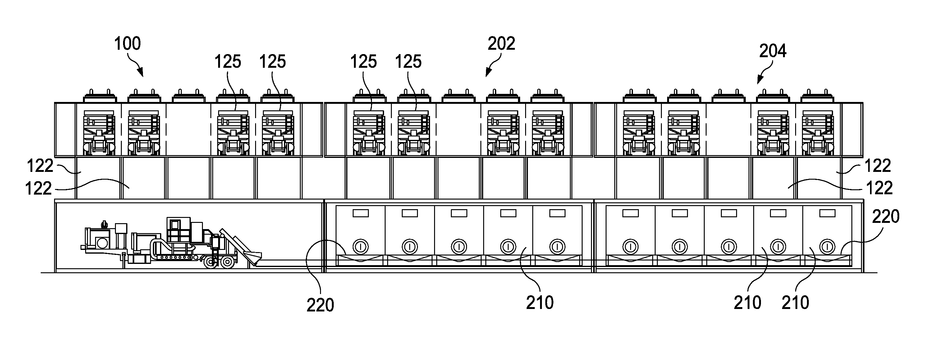
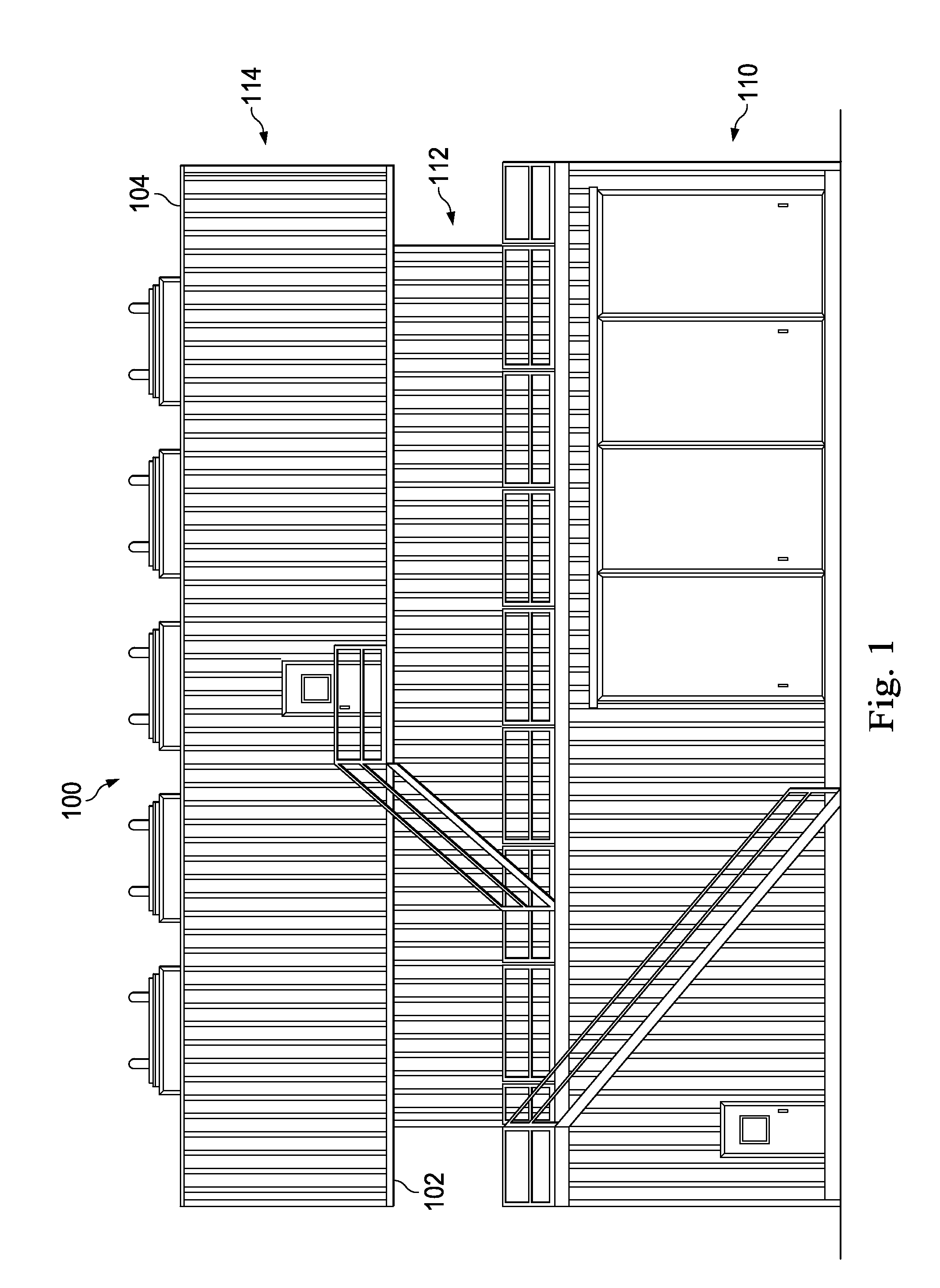
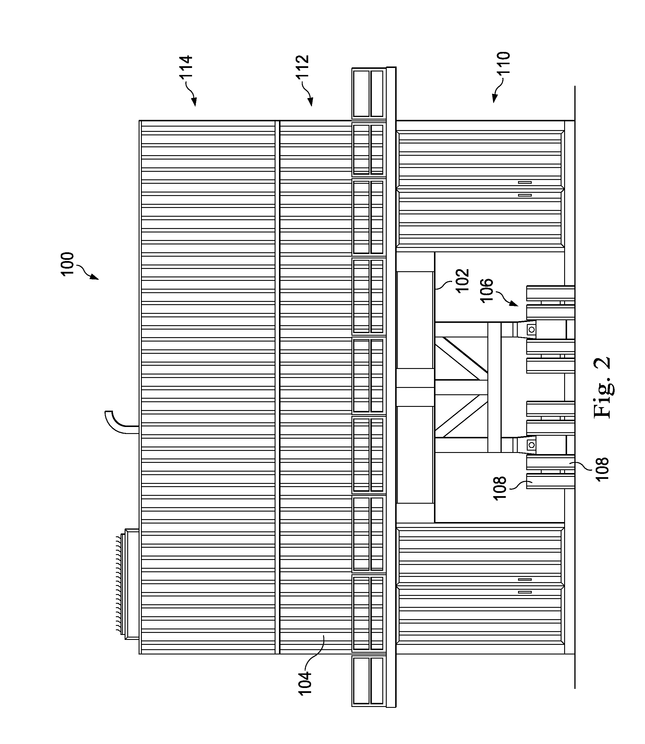
The patent is directed to an apparatus and method for integrating fracking pumps, fluid tanks, and piping systems on a mobile structure for use in a fracking procedure. The apparatus includes a frame structure carrying the fluid tanks and pumps, and an integrated piping system connected to the pumps and tanks. The method involves providing a mobile structure with a plurality of high-pressure fracking pumps, a fluid coupling system, and a fracking fluid tank. The mobile structure is then transported to a fracking site. The technical effects of the invention include higher efficiency, flexibility, and reduced costs for fracking operations.

Problems solved by technology

While separate trailers and skids may appear to simplify transportation, assembly of the equipment in harsh arctic weather conditions may present particular challenges.
Because of this, the interpiping connections present more opportunity for leaking, damage, and spills.
In addition, the harsh environment can make connecting the different equipment pieces difficult, which slows down operations and results in a less efficient set up.
Disconnection often results in additional spills.
Further exposure to harsh arctic elements may result in a higher chance of freeze up, further slowing processing.
In addition, because the fracking system is assembled on-site, a significant investment in time may be required.
This can increase the number of personnel needed to transport, set-up, and take down fracking systems.
In addition, because the assembly is done in the potentially harsh arctic conditions, there is an increased chance of crossed lines, mistakes, personnel accidents, and even spills.

Method used


Image

  • Integrated Arctic Fracking Apparatus and Methods
  • Integrated Arctic Fracking Apparatus and Methods
  • Integrated Arctic Fracking Apparatus and Methods

Examples


Embodiment Construction

[0031]It is to be understood that the following disclosure provides many different embodiments, or examples, for implementing different features of various embodiments. Specific examples of components and arrangements are described below to simplify the present disclosure. These are, of course, merely examples and are not intended to be limiting. In addition, the present disclosure may repeat reference numerals and / or letters in the various examples. This repetition is for the purpose of simplicity and clarity and does not in itself dictate a relationship between the various embodiments and / or configurations discussed. Moreover, the formation of a first feature over or on a second feature in the description that follows may include embodiments in which the first and second features are formed in direct contact, and may also include embodiments in which additional features may be formed interposing the first and second features, such that the first and second features may not be in d...


PUM


Abstract

An apparatus includes a frame structure and one or more fracking fluid tanks carried by the frame structure. The one or more fracking fluid tanks arranged to contain a fracking fluid usable during a fracking procedure. One or more fracking pumps may be carried by the frame structure, the one or more fracking pumps being configured to pump the fracking fluid to a wellhead of a wellbore at high pressure. An integrated piping system connects with the one or more fracking pumps to carry fracking fluid that was contained in the one or more fracking fluid tanks toward the one or more fracking pumps. Mobility-enabling structure supports the frame structure, the one or more fracking fluid tanks, the one or more fracking pumps, and the integrated piping system, the mobility enabling-structure being configured to enable conveyance of the apparatus to a fracking site.

Description

TECHNICAL FIELD[0001]This application claims priority to and the benefit of the filing date of U.S. Provisional Patent Application No. 61 / 770,157, filed Feb. 27, 2013, titled, “Integrated Arctic Fracking Apparatus and Methods” the entire content of which is incorporated herein by reference thereto.TECHNICAL FIELD[0002]The apparatus, systems, and methods described herein relate to an integrated fracking system that includes a frame structure that carries one or more fracking fluid tanks and one or more fracking pumps, and an integrated piping system connected to each fracking pump, and a mobility-enabling structure supporting the frame structure.BACKGROUND OF THE DISCLOSURE[0003]Hydraulic fracturing to stimulate a subterranean formation includes injecting a fracturing fluid through a wellbore into the formation at a pressure and flow rate at least sufficient to overcome the pressure of the reservoir and extend fractures into the formation. A high pressure line directs the fracturing ...

Claims


Application Information

Patent Timeline
Patent Type & Authority Applications(United States)
IPC IPC(8): E21B43/267
CPCE21B43/267E21B7/008E21B21/01E21B43/2607
Inventor KORACH, DONOVAN M.HUFF, ZACHARY T.
Owner NABORS ALASKA DRILLING
Learn More