
Method for single-fiber microscopy using intensity-pattern sampling and optimization-based reconstruction

a single-fiber microscopy and intensity-pattern technology, applied in the field of single-fiber microscopy and endoscopy, can solve the problems of large diameter, incompatibility with some applications, and large system bulk, and achieve the effect of image resolution

Inactive Publication Date: 2014-08-21
THE BOARD OF TRUSTEES OF THE LELAND STANFORD JUNIOR UNIV
View PDF28 Cites 15 Cited by
  • Summary
  • Abstract
  • Description
  • Claims
  • Application Information

AI Technical Summary

Benefits of technology

The present invention is a method for imaging using a single optical fiber that can resolve more object features than the number of optical modes in the fiber. This is done using a non-local reconstruction technique that increases the number of resolvable features. The imaging system is calibrated to produce a set of spatial light modulator patterns that can be used to interrogate an object. The invention has particular applications in biological imaging, such as endoscopy, where it can achieve a higher image resolution than prior-art methods.

Problems solved by technology

Unfortunately, due to the large number of optical fibers required, these systems are bulky and have a relatively large diameter.
As a result, they are incompatible for some applications.
When used, the large diameter can give rise to procedural complications and / or patient discomfort.
Further, due in part to the limited number of optical fibers in the optical fiber bundle, the image quality of such endoscopes is limited.
Unfortunately, the number of independently resolvable image features of the object is limited to the total number of spatial modes, per polarization, that propagate through the optical fiber.
Because this alternative method treats the high-spatial-frequency features of speckle as noise that must be smoothed out, the number of resolvable features is still limited to the total number of spatial modes, per polarization, that propagate through the optical fiber, however.

Method used


Image

  • Method for single-fiber microscopy using intensity-pattern sampling and optimization-based reconstruction
  • Method for single-fiber microscopy using intensity-pattern sampling and optimization-based reconstruction
  • Method for single-fiber microscopy using intensity-pattern sampling and optimization-based reconstruction

Examples


Embodiment Construction

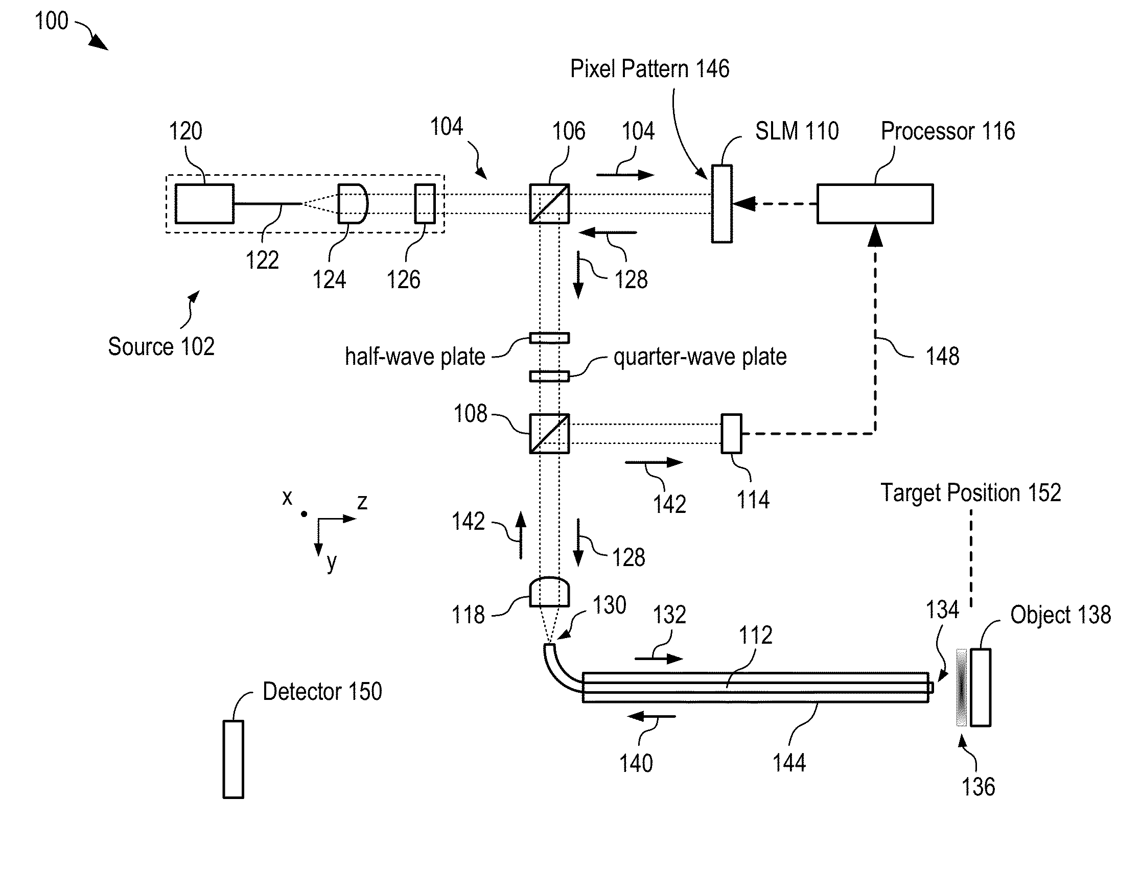
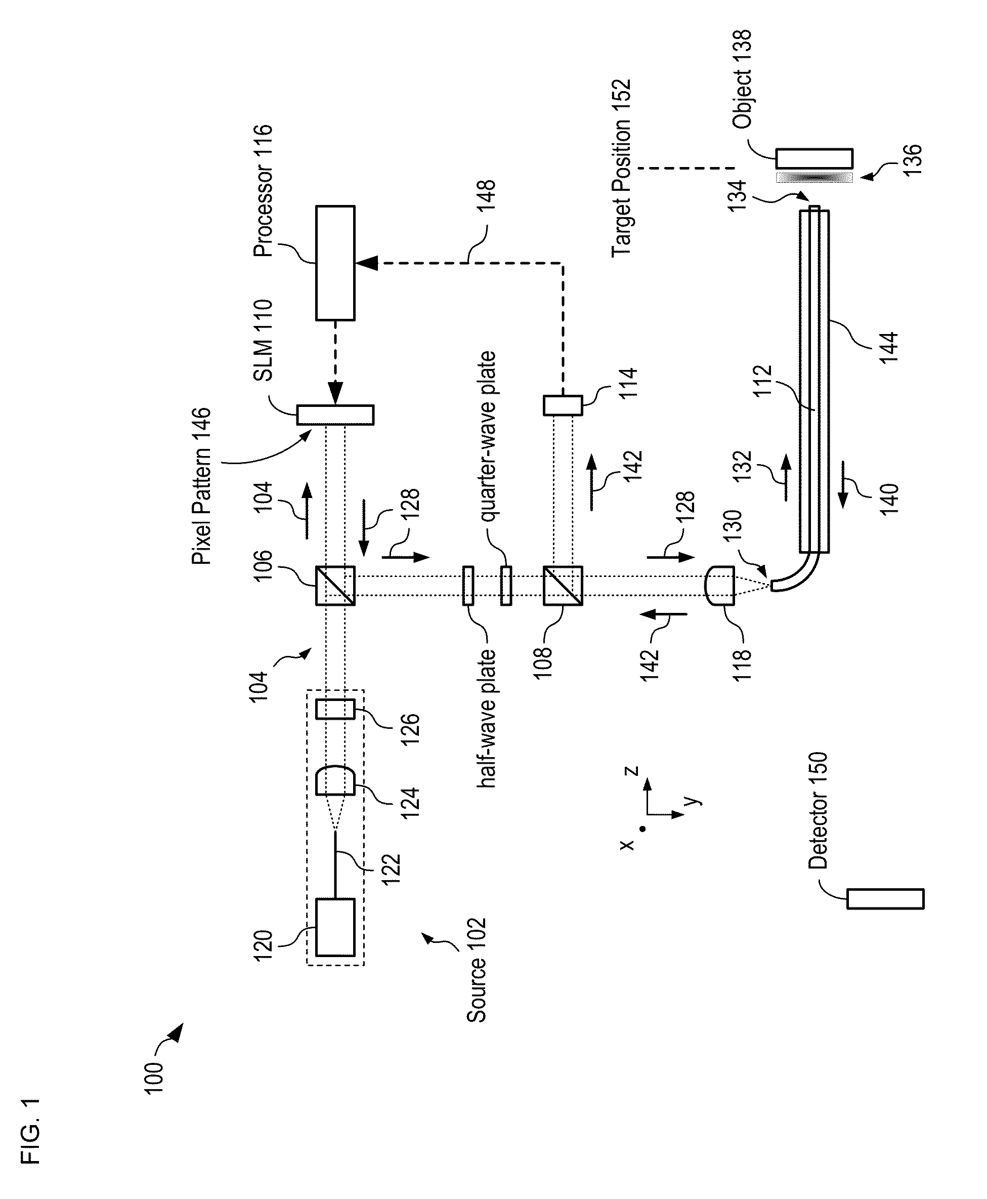
[0027]FIG. 1 depicts a schematic diagram of a portion of an imaging system in accordance with an illustrative embodiment of the present invention. Imager 100 includes source 102, conventional beam splitters 106 and 108, SLM 110, optical fiber 112, power monitor 114, processor 116, and lens 118. Imager 100 is operative for interrogating object 138 with a series of intensity patterns, whose configurations are controlled by SLM 110.

[0028]Source 102 includes laser 120, polarization-maintaining, single-mode optical fiber 122, collimator 124, and linear polarizer 126. Laser 120 emits 1550-nm light, which is coupled through polarization-maintaining, single-mode optical fiber 122 to collimator 124. Collimator 124 collimates the light, which passes through linear polarizer 126 as beam 104. One skilled in the art will recognize that the desired wavelength of beam 104 depends on the application for which imager 100 is intended.

[0029]Spatial-light modulator (SLM) 110 is a phase-only nematic liq...


PUM


Abstract

A method for imaging an object with resolution that exceeds the number of spatial modes per polarization in a multimode fiber is disclosed. In some embodiments, the object is interrogated with a plurality of non-spot-sized intensity patterns and the optical power reflected by the object is detected for each intensity pattern. The plurality of optical power values is then used in a non-local reconstruction based on an optimization approach to reconstruct an image of the object, where the image has resolution up to four times greater than provided by prior-art multimode fiber-based imaging methods.

Description

CROSS REFERENCE TO RELATED APPLICATIONS[0001]This application claims the benefit of U.S. Provisional Application Ser. No. 61 / 766,432, filed Feb. 19, 2013, entitled “Random Pattern Sampling and Optimization-Based Reconstruction In Single-Fiber Microscopy,” (Attorney Docket 146-036PR1), which is incorporated herein by reference. If there are any contradictions or inconsistencies in language between this application and the case that has been incorporated by reference that might affect the interpretation of the claims in this case, the claims in this case should be interpreted to be consistent with the language in this case.FIELD OF THE INVENTION[0002]The present invention relates to imaging in general, and, more particularly, to single-fiber microscopy and endoscopy.BACKGROUND OF THE INVENTION[0003]A conventional flexible fiber-based microscope, such as an endoscope, typically includes a bundle containing thousands of optical fibers, a high-power light source, and a miniature camera. ...

Claims


Application Information

Patent Timeline
IPC IPC(8): A61B1/07
CPCA61B1/07A61B1/00009A61B1/00165A61B1/04
Inventor MAHALATI, REZA NASIRIGU, RUO YUKAHN, JOSEPH M.
Owner THE BOARD OF TRUSTEES OF THE LELAND STANFORD JUNIOR UNIV
Learn More