
Interactive projector and interactive projection system

a projection system and projector technology, applied in the field of interactive projection systems, can solve the problem that the distance between the tip of the pointing element and the screen is not necessarily sufficient, and achieve the effect of reducing the distance between the tip of the pointing element and the screen

Active Publication Date: 2017-02-28
SEIKO EPSON CORP
View PDF10 Cites 2 Cited by
  • Summary
  • Abstract
  • Description
  • Claims
  • Application Information

AI Technical Summary

Benefits of technology

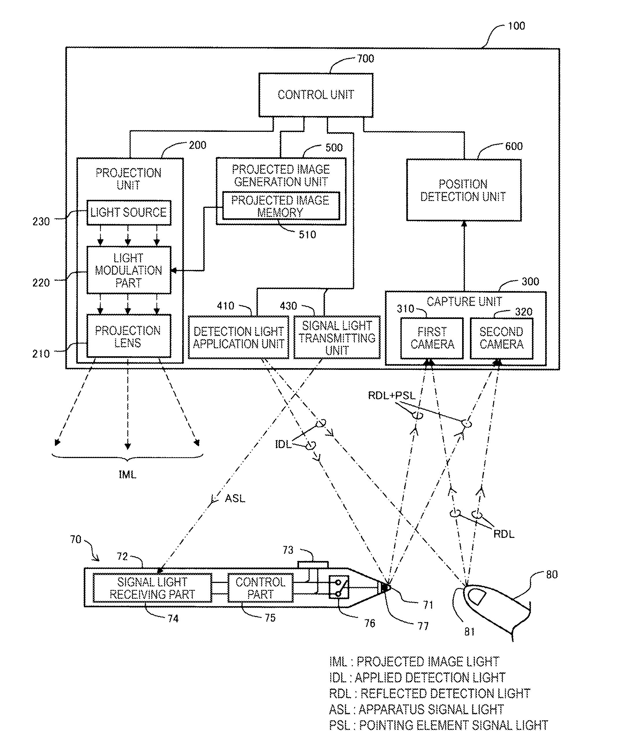
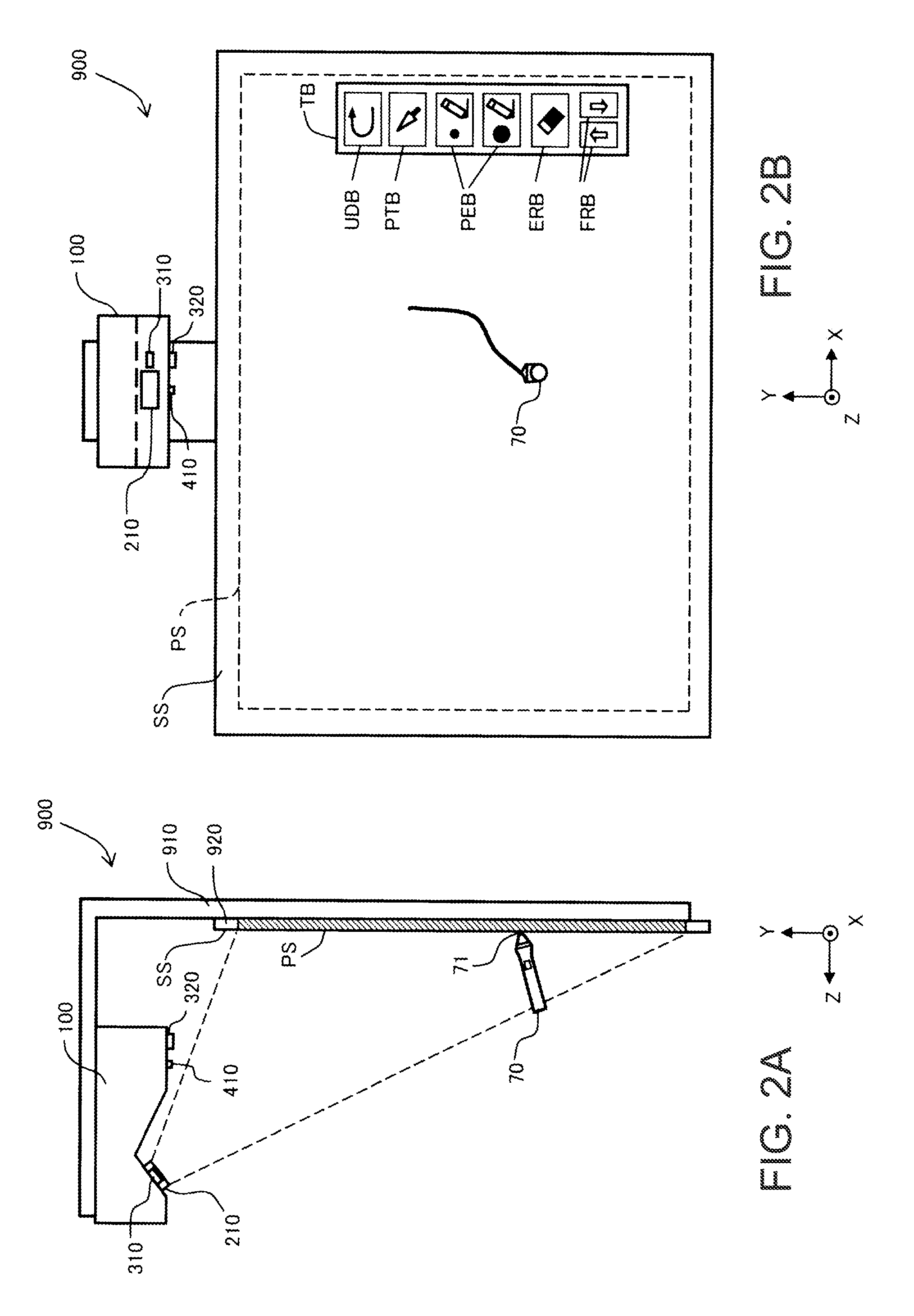
[0009]According to the interactive projector, resolution of the image captured by the second camera is higher with respect to the normal direction of the projected screen than that of the image captured by the first camera, and thus, the distance of the pointing element from the projected screen may be determined with higher accuracy.
[0011]According to this configuration, the distance of the pointing element from the projected screen near the projected screen may be determined more accurately.
[0013]According to this configuration, the distance of the pointing element from the projected screen near the projected screen may be determined more accurately.
[0015]According to this configuration, the distance of the pointing element from the projected screen near the projected screen may be determined more accurately.
[0017]According to this configuration, the distance of the pointing element from the projected screen may be determined more accurately.

Problems solved by technology

However, in related art, the detection accuracy of the distance between the tip of the pointing element and the screen is not necessarily sufficient and improvement of the detection accuracy is desired.

Method used


Image

  • Interactive projector and interactive projection system
  • Interactive projector and interactive projection system
  • Interactive projector and interactive projection system

Examples


modified examples

[0087]The invention is not limited to the above-described examples and embodiments, but may be implemented in various forms without departing from the scope thereof. For example, the following modifications may be made.

modified example 1

[0088]In the embodiments, the capture unit 300 has the two cameras 310, 320, however, the capture unit 300 may have three or more cameras. In the latter case, three-dimensional coordinates (X, Y, Z) are determined based on m (m is an integer number equal to or more than three) images captured by m cameras. For example, three-dimensional coordinates may be respectively obtained using mC2 combinations obtained by arbitrary selection of two images from the m images, and the final three-dimensional coordinates may be determined using average values of them. In this manner, the detection accuracy of the three-dimensional coordinates can be further improved.

modified example 2

[0089]In the embodiments, the interactive projection system 900 is operable in the whiteboard mode and the PC interactive mode, however, the system may be adapted to operate only in one mode of them. Further, the interactive projection system 900 may be adapted to operate only in another mode than those two modes, and further, may be adapted to operate in a plurality of modes including the two modes.


PUM


Abstract

An interactive projector includes a projection section, a plurality of cameras, and a position detection section for detecting a three-dimensional position of the pointing element based on images captured by the plurality of cameras. Defining a unit vector representing a normal direction of the projected screen as a projected-screen normal vector, a unit vector representing a direction of an optical axis of the first camera as a first optical axis vector, and a unit vector representing a direction of an optical axis of the second camera as a second optical axis vector, the first camera and the second camera are arranged such that an absolute value of an inner product of the second optical axis vector and the projected-screen normal vector is smaller than an absolute value of an inner product of the first optical axis vector and the projected-screen normal vector.

Description

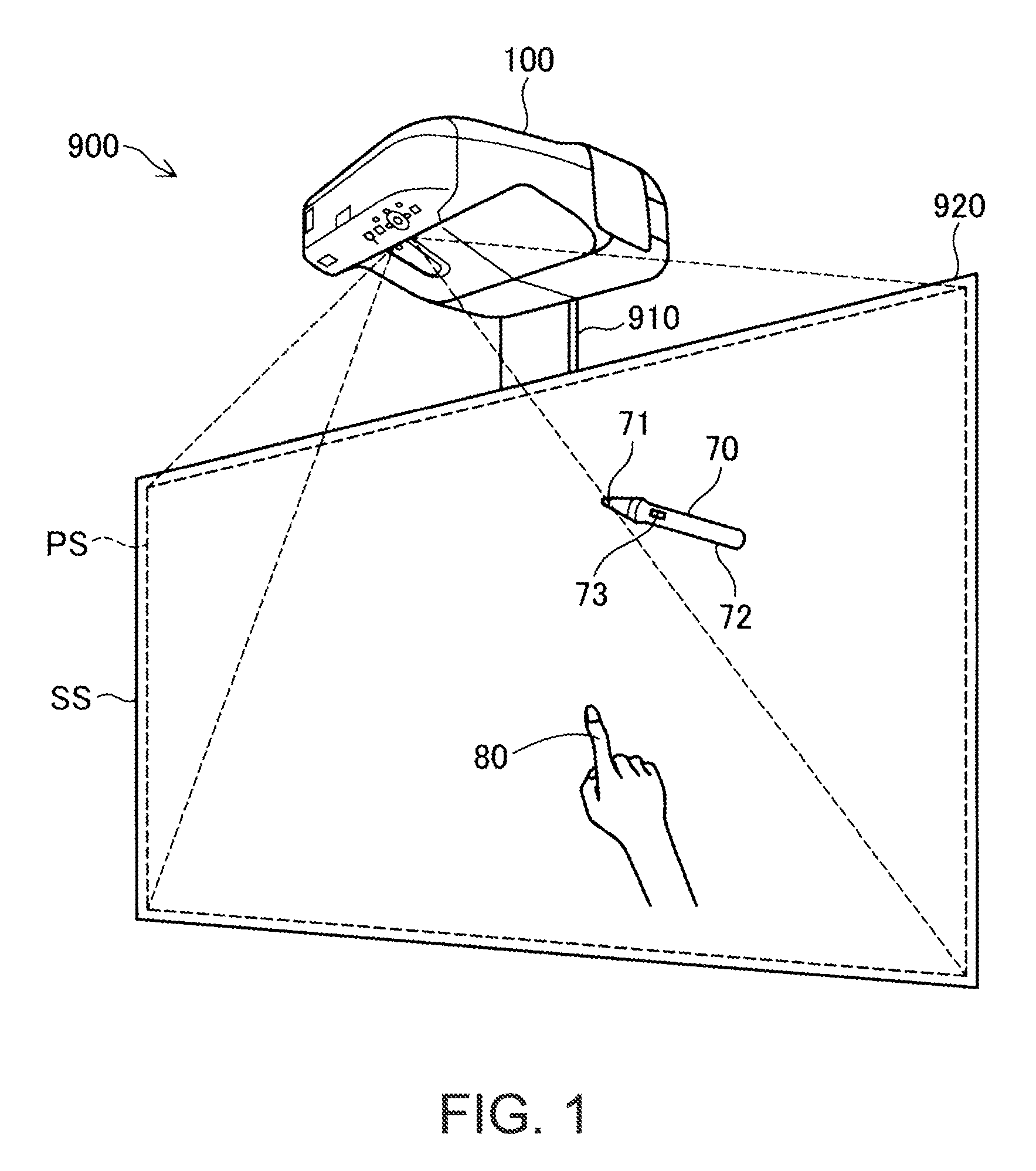
[0001]The entire disclosure of Japanese Patent Application No. 2015-065630, filed Mar. 27, 2015 is expressly incorporated by reference herein.BACKGROUND[0002]1. Technical Field[0003]The present invention relates to an interactive projector capable of receiving an instruction on a projected screen by a pointing element of a user, and a system thereof.[0004]2. Related Art[0005]Patent Document 1 (JP-A-2012-150636) discloses a projection display apparatus (projector) capable of projecting a projected screen on a screen, and capturing an image containing an object such as a finger using a camera and detecting a position of the object using the captured image. The object such as a finger is used as a pointing element for giving an instruction on a projected screen. That is, the projector recognizes that a predetermined instruction of drawing or the like is input to the projected screen when the tip of the object is in contact with the screen, and redraws the projected screen according to ...

Claims


Application Information

Patent Timeline
Patent Type & Authority Patents(United States)
IPC IPC(8): H04N9/31G06F3/0346G06F3/03
CPCG06F3/0346G06F3/0325H04N9/31H04N9/3194G06F3/0425
Inventor KUBOTA, SHINJI
Owner SEIKO EPSON CORP
Learn More