
Digital subscriber line management using virtual noise calculation

a technology of virtual noise and subscriber line, applied in the field of digital subscriber line management, can solve the problems of dsl transceivers losing synchronization with each other, cross talk from neighboring lines operating at the same high frequency becomes more of a problem, and the level of cross talk noise will vary significantly, so as to achieve the effect of reducing the number of transceivers and increasing the accuracy of calculation and application of virtual nois

Active Publication Date: 2014-08-21
BRITISH TELECOMM PLC
View PDF4 Cites 2 Cited by
  • Summary
  • Abstract
  • Description
  • Claims
  • Application Information

AI Technical Summary

Benefits of technology

The patent describes a method for reducing noise in a communication system. The method involves measuring the noise and creating a virtual noise mask that can be used to filter out the noise. This virtual noise mask is generated by a central management device or can be performed by the transceiver units themselves. The method is particularly useful when cross talk cancellation techniques are utilized, as it becomes more important to accurately calculate and apply the virtual noise mask. The technical effect of this patent is to improve the accuracy of communication systems by reducing noise and interference.

Problems solved by technology

Unfortunately, at these much higher frequencies cross talk from neighboring lines operating at the same high frequencies becomes more of a problem.
A particular problem of cross noise when a system has low power modes is that the level of cross talk noise will vary significantly when a neighboring line is in a low power mode, compared to when it is in a high power mode and actively transmitting and / or receiving data.
If the noise experienced by the line becomes too great to sustain the line rate at which the line synchronized, the connection will fail and the DSL transceivers will lose synchronization with each other.
As noted above, the use of low power modes can cause the noise environment of a DSL line to change dramatically over time.
If at a subsequent time the second line then “wakes up” and goes into a high power mode, the affect on the noise environment of the first line may be such that it can no longer sustain the line rate at which it originally synched and so cause the first line to drop out.
Furthermore, US 2010 / 0254442 does not teach a method of selecting which tones to use as break points in the virtual noise mask.

Method used


Image

  • Digital subscriber line management using virtual noise calculation
  • Digital subscriber line management using virtual noise calculation
  • Digital subscriber line management using virtual noise calculation

Examples


Embodiment Construction

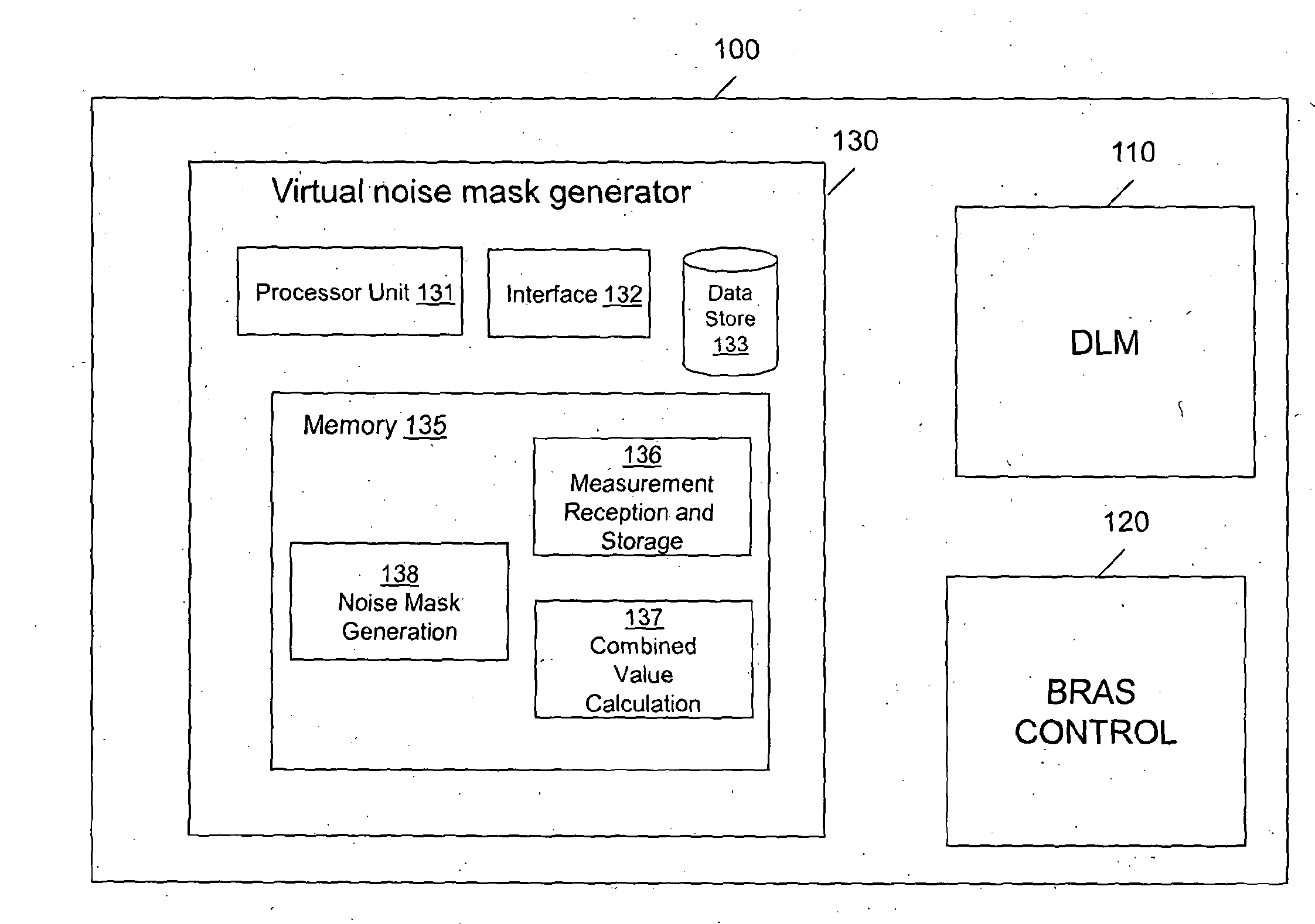
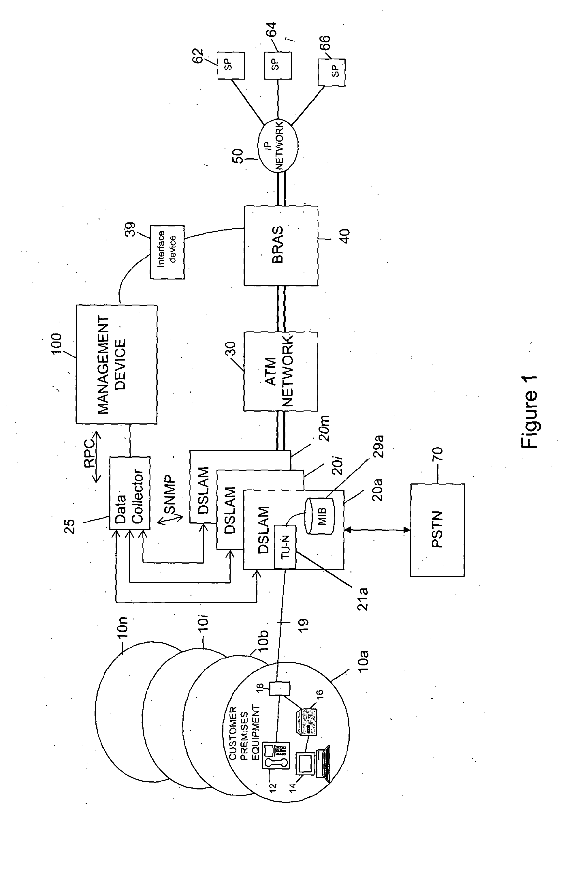
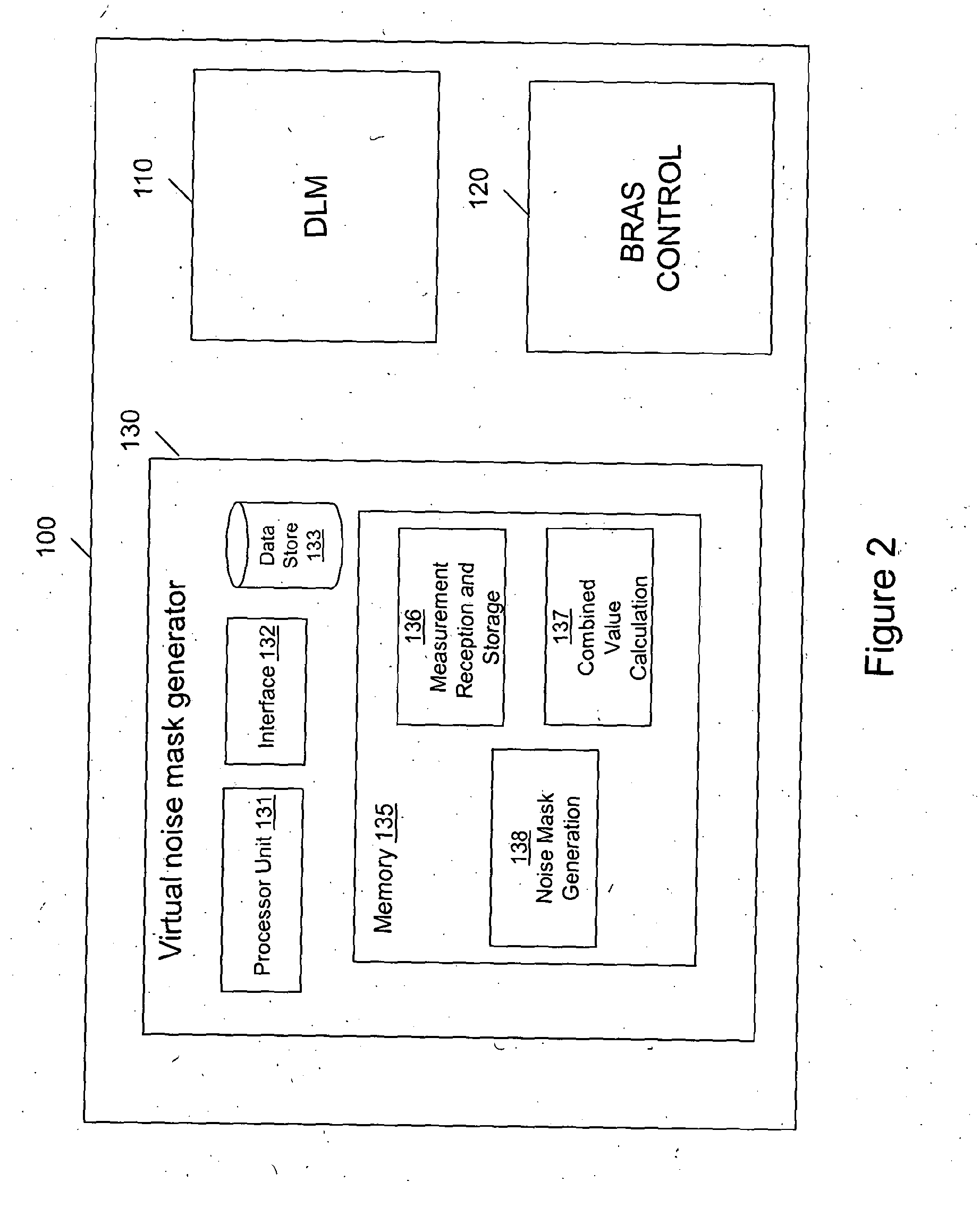
[0031]One embodiment described below uses a management device 100 to perform two principal functions—Broadband Remote Access Server (BRAS) provisioning and Dynamic Line

[0032]Management (DLM). The BRAS provisioning is not relevant to the present application and is therefore not described any further here but it is described in detail in co-pending International patent applications WO2007 / 012869 and WO2007 / 012867, for readers interested in the particulars of the preferred methods of BRAS provisioning applicable to the main embodiment.

[0033]As for the DLM function, this is desirable in the main embodiment because the downstream and upstream speeds of the DSL connections controlled by the management device of the main embodiment rate adapt to the highest speeds the line can support. As the DSL connections are running at their maximum limits they are more susceptible to noise which can cause errors and spontaneous resynchronizations (re-synchs).

[0034]In overview, the role of the DLM func...


PUM


Abstract

A digital subscriber line management system is provided. It comprises a device for calculating a set of values specifying a virtual noise mask. The device includes a receiver for receiving or otherwise obtaining a set of measurements of noise levels experienced at a digital subscriber line transceiver at each of a plurality of frequencies at different times, and a processor for calculating, in respect or each frequency, a combined value based on a plurality of measurements taken at different times, and for generating the set of values specifying a virtual noise mask in dependence upon the combined values.

Description

PRIORITY CLAIM[0001]The present application is a National Phase entry of PCT Application No. PCT / GB2012 / 000747, filed Sep. 28, 2012, which claims priority from EP Patent Application No. 11250602.7, filed Jun. 20, 2011, and EP Patent Application No. 11250832.0, filed Sep. 30, 2011, said applications being hereby incorporated by reference herein in their entireties.TECHNICAL FIELD[0002]Embodiments relate to Digital Subscriber Line (DSL) management and especially management of high bandwidth DSL types such as high speed Asynchronous DSL (ADSL) and Very high speed Digital Subscriber Line (VDSL).BACKGROUND[0003]DSL systems which operate at very high bandwidths tend to do so by employing higher frequency portions of the spectrum which becomes more feasible as the length of each line shortens (as fiber is pushed further towards the edges of the access network—e.g. Fiber to the Cabinet (FttC) and Fiber to the Drop Point (FttDP). Unfortunately, at these much higher frequencies cross talk fro...

Claims


Application Information

Patent Timeline
Patent Type & Authority Applications(United States)
IPC IPC(8): H04B3/32
CPCH04B3/32H04J3/10H04M3/34
Inventor CROOT, CHRISTOPHER MARCUS
Owner BRITISH TELECOMM PLC
Learn More