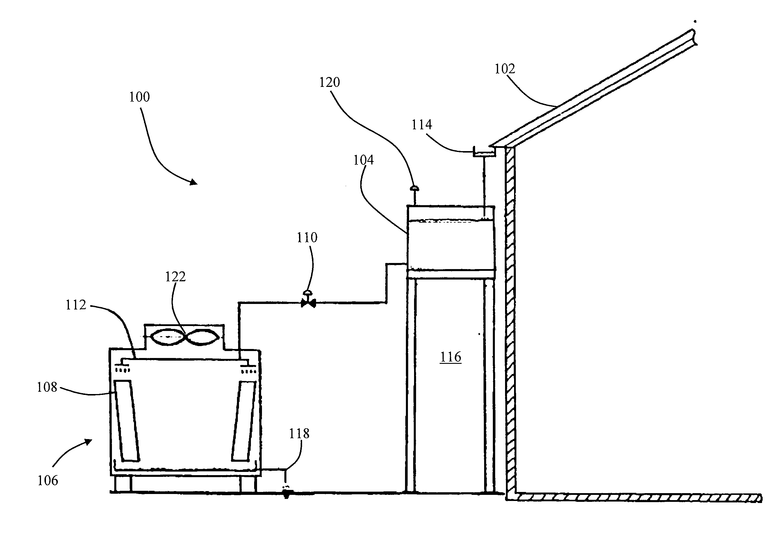
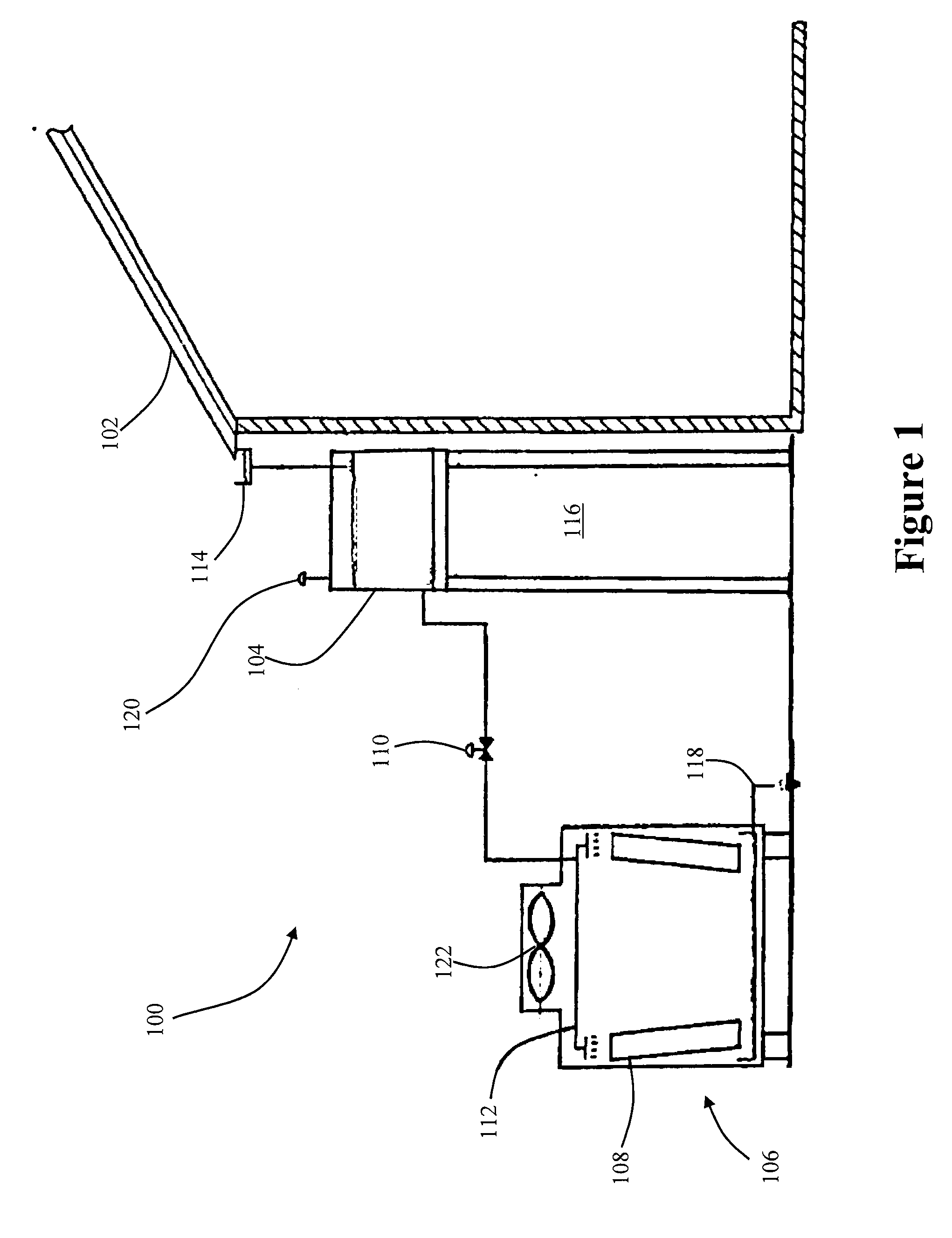
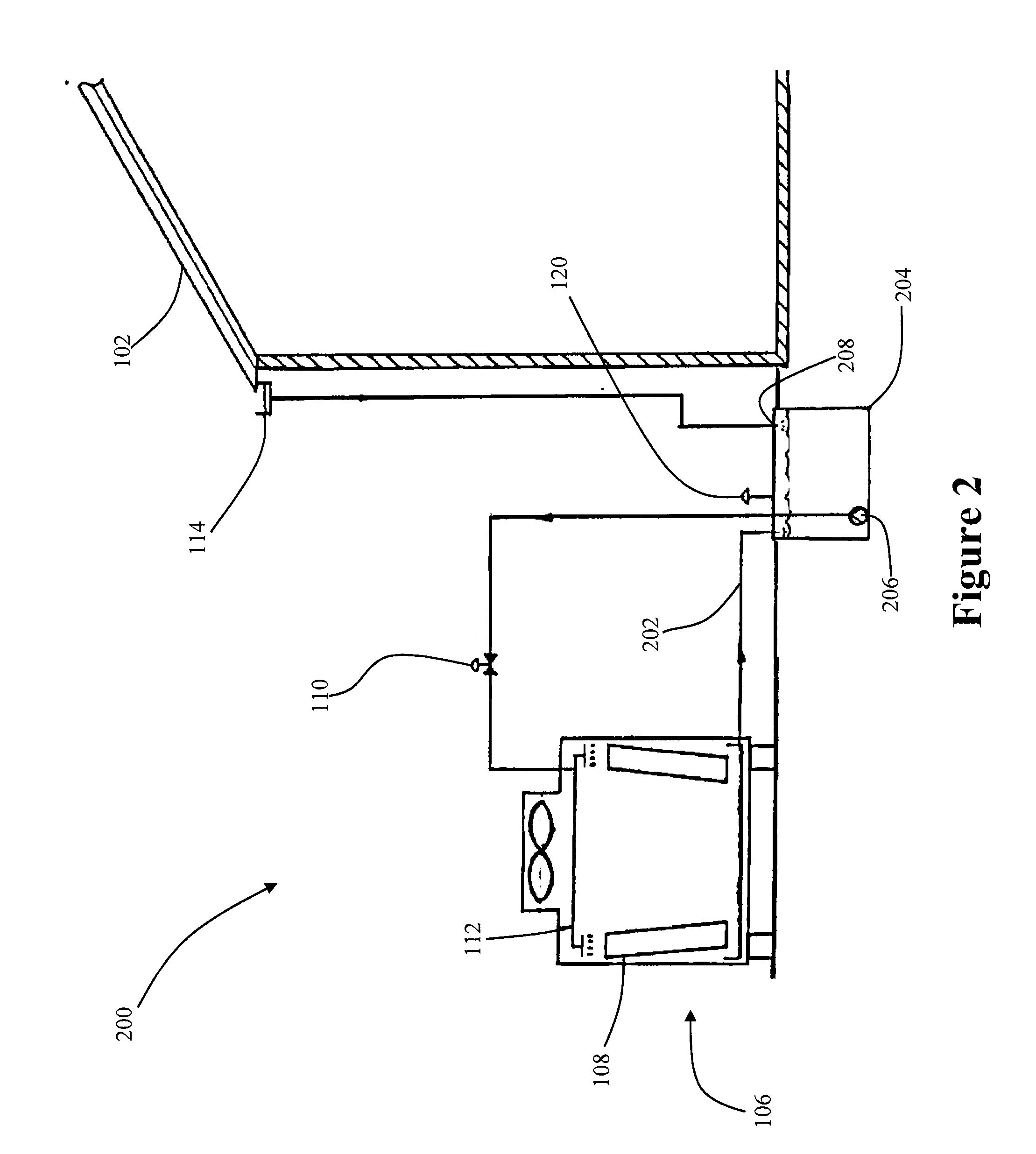
System for Reducing the Condensing Temperature of a Refrigeration or Air Conditioning System by Utilizing Harvested Rainwater
a technology of refrigeration or air conditioning system and rainwater harvesting, which is applied in the direction of indirect heat exchangers, lighting and heating apparatus, heating types, etc., can solve the problems of requiring more maintenance time, consuming nearly half the energy per ton of water cooled and evaporative cooled equipment, and high initial cost of types of systems, so as to reduce the effect of suspended solids
- Summary
- Abstract
- Description
- Claims
- Application Information
AI Technical Summary
Benefits of technology
Problems solved by technology
Method used
Image

Examples
Embodiment Construction
[0053]The embodiments of the present invention described below are not intended to be exhaustive or to limit the invention to the precise forms disclosed in the following detailed description. Rather, the embodiments are chosen and described so that others skilled in the art may appreciate and understand the principles and practices of the present invention.
[0054]Unless defined otherwise, all technical and scientific terms used herein have the same meaning as commonly understood by one of ordinary skill in the art to which this invention belongs. Although any method and materials similar or equivalent to those described herein can be used in the practice or testing of the present invention, illustrative methods and materials are now described.
[0055]Generally speaking, the present application relates to systems and methods for retrofitting existing air-cooled condensers and condensing units (or new condensers or condensing units as would be designed by air conditioning unit manufactu...
PUM
 Abstract
Description
Claims
Application Information
 - R&D
- Intellectual Property
- Life Sciences
- Materials
- Tech Scout
- Unparalleled Data Quality
- Higher Quality Content
- 60% Fewer Hallucinations
Browse by: Latest US Patents, China's latest patents, Technical Efficacy Thesaurus, Application Domain, Technology Topic, Popular Technical Reports.
© 2025 PatSnap. All rights reserved.Legal|Privacy policy|Modern Slavery Act Transparency Statement|Sitemap|About US| Contact US: help@patsnap.com