
Optical module with common part reference for motor vehicle lighting and/or signalling

a technology of optical modules and parts, applied in fixed installations, lighting and heating apparatus, lighting support devices, etc., can solve the problems of putting a strain on affecting the overall cost of lighting functions, etc., to achieve the effect of increasing the level of accuracy and reliability of the module, reducing the cost of lighting functions implemented by optical modules according to the invention, and increasing the reliability of the assembly

Active Publication Date: 2014-08-14
VALEO VISION SA
View PDF13 Cites 30 Cited by
  • Summary
  • Abstract
  • Description
  • Claims
  • Application Information

AI Technical Summary

Benefits of technology

The invention reduces the cost of an optical module used in vehicles by eliminating a part. It also improves the reliability of the assembly by reducing the chain of banks between the light source and the focusing device, which increases accuracy and reliability.

Problems solved by technology

This part thus represents a cost which puts a strain on the overall cost of the lighting function.
Another drawback lies in the fact that this support is a distinct and intermediate part between the assembly targeted above and the optical part.

Method used


Image

  • Optical module with common part reference for motor vehicle lighting and/or signalling
  • Optical module with common part reference for motor vehicle lighting and/or signalling
  • Optical module with common part reference for motor vehicle lighting and/or signalling

Examples


Embodiment Construction

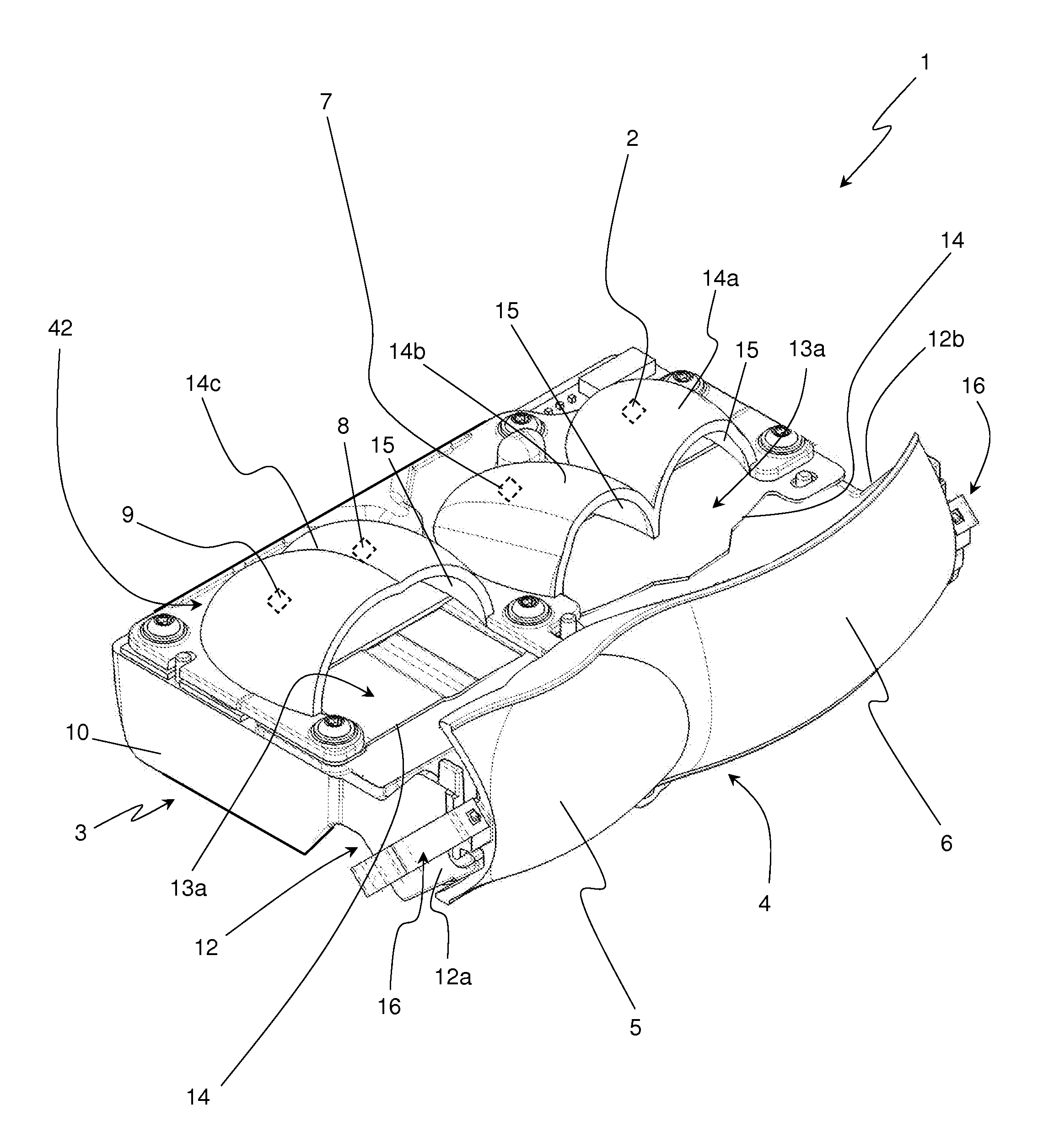
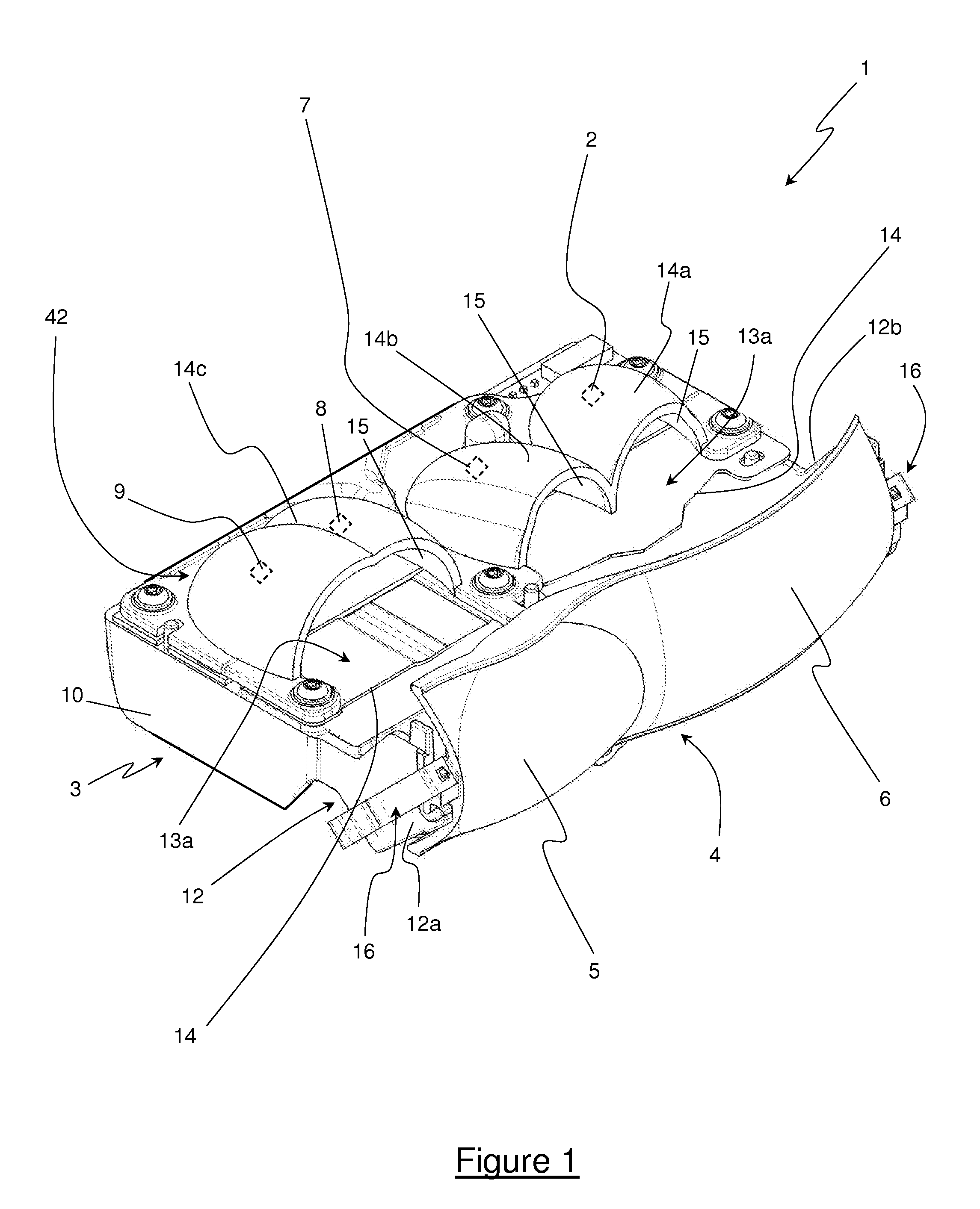
[0041]FIG. 1 illustrates an optical module 1 according to the invention. Such an optical module 1 is intended to be incorporated in a front headlight or headlamp of a motor vehicle. The function of this optical module 1 is to generate at least one light beam and to project this beam onto a road taken by the vehicle. Such an optical module 1 participates in the production of a beam of code type or of a beam of road type, the description below being limited to the example of the beam of code type.

[0042]This optical module 1 comprises at least one light source 2 which forms the element generating the light rays of the light beam. Since this light source 2 releases heat, the optical module 1 also comprises a cooling device 3 responsible for picking up at least the heat generated by the light source 2 and dissipating it into the air surrounding the optical module 1. This cooling device 3 is notably formed by a heat-sink or dissipater manufactured in aluminum alloy.

[0043]The optical modul...


PUM


Abstract

An optical module DE for a lighting and / or signaling device of a vehicle, comprising at least one light source capable of generating a light beam, a cooling device capable of dissipating heat and a device for focusing the light beam, characterized in that the focusing device is borne directly by the cooling device.Application to motor vehicles.

Description

CROSS-REFERENCE TO RELATED APPLICATIONS[0001]This application claims priority to PCT Application PCT / EP2012 / 067777 filed Sep. 12, 2012, and also to French Application No. 1158106 filed Sep. 13, 2011, which are incorporated herein by reference and made a part hereof.BACKGROUND OF THE INVENTION[0002]1. Field of the Invention[0003]The technical field of the present invention is that of optical modules intended to produce a light beam in order to light a road taken by a vehicle bearing this optical module. Such an optical module is particularly applicable when it is installed inside a lighting and / or signaling device for a motor vehicle.[0004]2. Description of the Related Art[0005]It is known practice to produce a light function on a motor vehicle by focusing light rays emitted by a light source. The optical parts used to focus these light rays are, generally, installed between the light source, for example a xenon lamp, and an outer lens enclosing a headlight which receives this assemb...

Claims


Application Information

Patent Timeline
Patent Type & Authority Applications(United States)
IPC IPC(8): F21S8/10F21W107/10
CPCF21S48/1109F21S48/1159F21S48/1216F21S48/1266F21S48/1305F21S48/1388F21S48/321F21S48/328F21S48/10F21S41/148F21S41/151F21S41/192F21S41/26F21S41/295F21S41/321F21S41/33F21S41/36F21S41/365F21S41/39F21S41/43F21S41/47F21S45/48F21S45/49F21S41/00
Inventor BLANDIN, JONATHANMORNET, ERICPEREZ, MAGDALENA
Owner VALEO VISION SA
Learn More