High Voltage Insulation System And A High Voltage Inductive Device Comprising Such An Insulation System

Active Publication Date: 2014-08-14
HITACHI ENERGY SWITZERLAND AG
View PDF1 Cites 0 Cited by
  • Summary
  • Abstract
  • Description
  • Claims
  • Application Information

AI Technical Summary

Benefits of technology

The present patent aims to provide an improved insulation system for a winding structure that increases the electric withstand strength of the inductive device. The system is designed to be more robust and simpler to manufacture, with a simplified production process and design. The system also improves the performance of the creepage path, which provides better protection against electrical aretry. Overall, the technical effects of the present patent include improved insulation and enhanced safety and reliability of the winding structure.

Problems solved by technology

Moreover, due to the high powers involved, energy losses generate such quantities of heat in for instance inductive elements that cooling may be necessary.
A drawback with the prior art is that they do not provide sufficient dielectric properties on both ends of the winding in some cases, for example in some high voltage direct current applications (HVDC).

Method used


Image

  • High Voltage Insulation System And A High Voltage Inductive Device Comprising Such An Insulation System
  • High Voltage Insulation System And A High Voltage Inductive Device Comprising Such An Insulation System
  • High Voltage Insulation System And A High Voltage Inductive Device Comprising Such An Insulation System

Examples


Embodiment Construction

[0035]The inventive concept will now be described more fully hereinafter with reference to the accompanying drawings, in which certain embodiments of the inventive concept are shown. The inventive concept may, however, be embodied in many different forms and should not be construed as limited to the embodiments set forth herein; rather, these embodiments are provided by way of example so that this disclosure will be thorough and complete, and will fully convey the scope of the inventive concept to those skilled in the art.

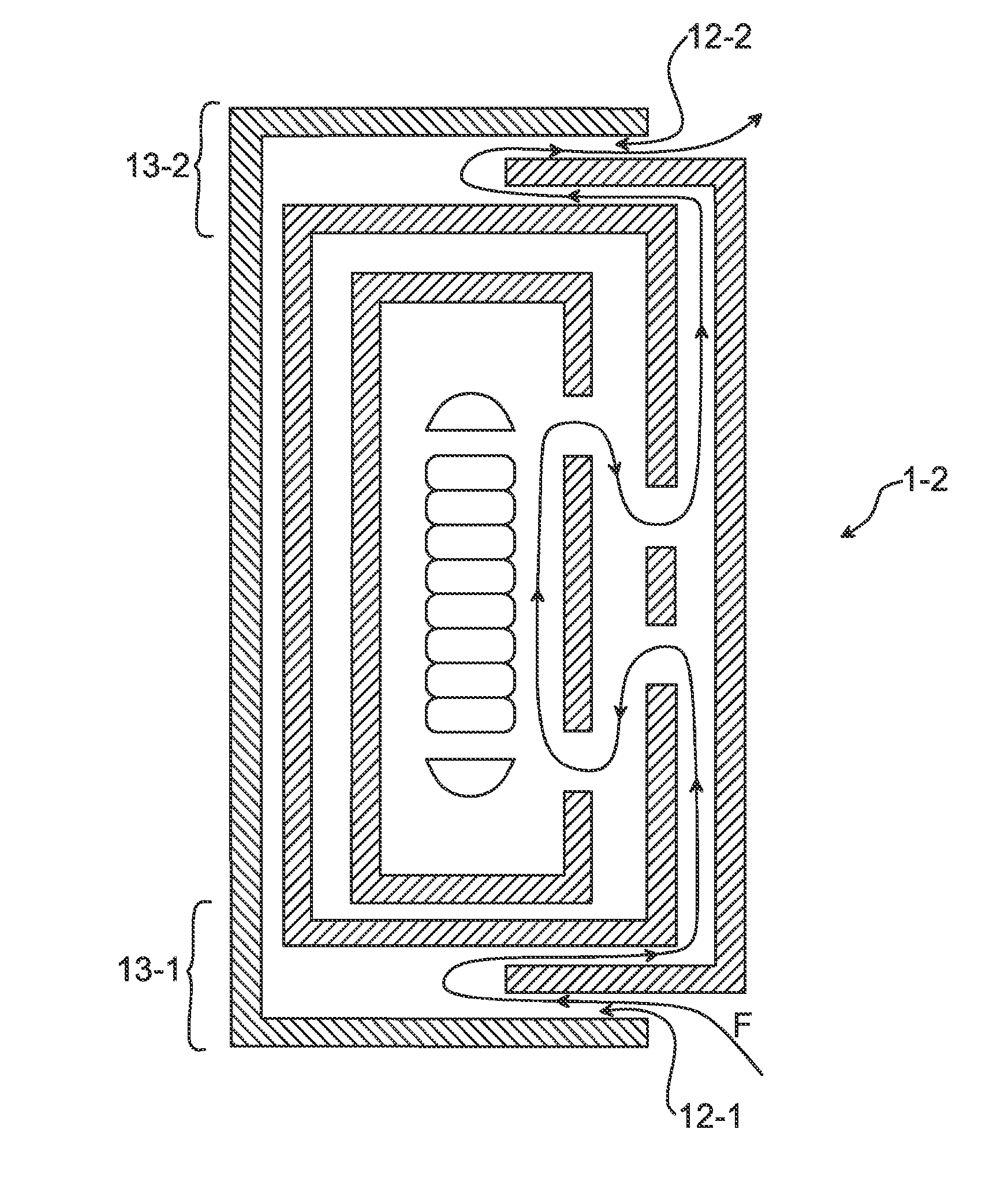
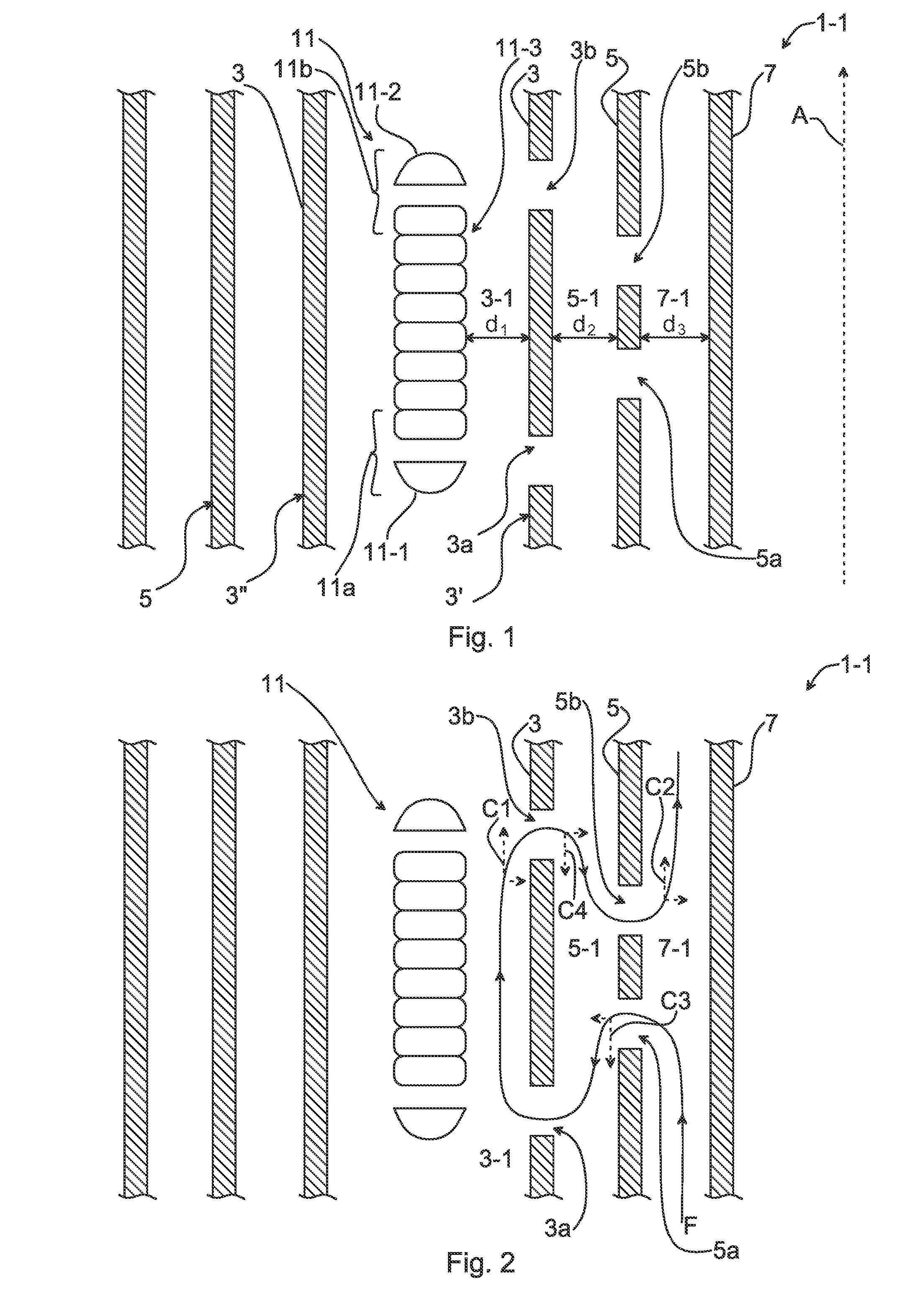
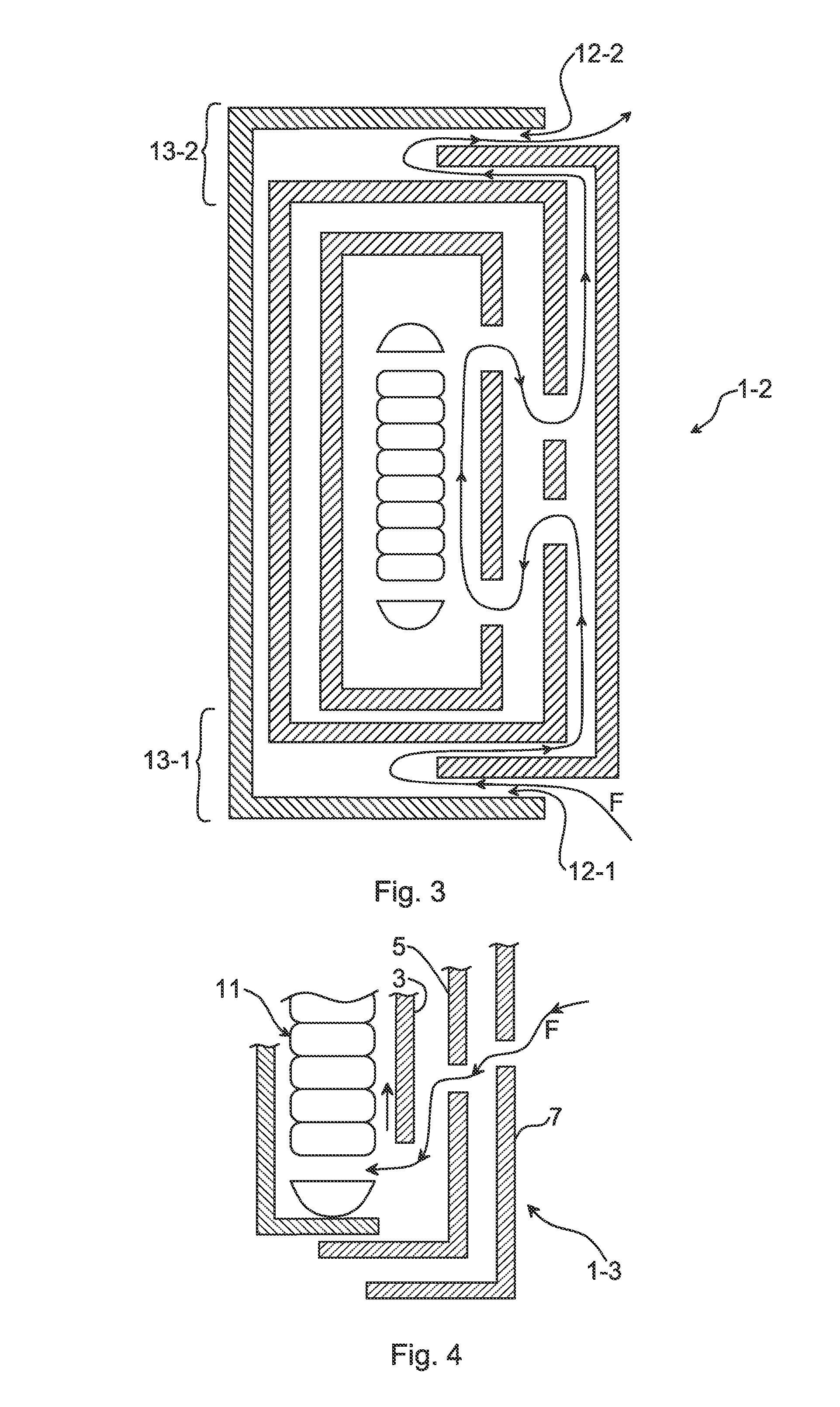
[0036]Examples of an insulation system for electrically insulating a winding structure having a first end portion and a second end portion are presented in the following. The insulation system comprises an innermost barrier pair arranged to cover a majority of the winding structure in the axial direction of the winding structure inside and outside the barrier structure relative the curvature of winding turns of windings of the winding structure. At least one barrie...


PUM


Abstract

An insulation system for a winding structure. The insulation system includes an innermost barrier pair arranged to cover a majority of the winding structure in the axial direction of the winding structure inside and outside the barrier structure relative the curvature of winding turns of windings of the winding structure, wherein at least one barrier of the innermost barrier pair defines a first flow path allowing flow of a dielectric fluid mainly in a first axial direction between the winding structure and the at least one barrier when the insulation system is in a assembled state; and a first outer barrier arranged radially inwards or radially outwards relative each barrier of the innermost barrier pair, wherein the first outer barrier defines a second flow path, parallel to the first flow path, allowing flow of a dielectric fluid mainly in a second axial direction opposite the first axial direction.

Description

FIELD OF THE INVENTION[0001]The present disclosure generally relates to high voltage power systems and in particular to an insulation system for an inductive device in a high voltage power system and to a high voltage inductive device comprising such an insulation system.BACKGROUND OF THE INVENTION[0002]In high voltage power systems such as those handling 100 kV and above, proper insulation of equipment such as inductive devices is necessary so as to ensure the safe operation thereof. Moreover, due to the high powers involved, energy losses generate such quantities of heat in for instance inductive elements that cooling may be necessary.[0003]Windings in high voltage inductive devices such as reactors and transformers are typically cooled by means of a dielectric fluid such as transformer oil, which can absorb the heat generated in the winding. When oil is absorbing heat in the winding, it has to escape from the winding and be replaced by cool oil which can absorb additional heat. T...

Claims


Application Information

Patent Timeline
IPC IPC(8): H01F27/32
CPCH01F27/322H01F27/12H01F27/08H01F27/32
Inventor ERIKSSON, ANDERS BOWEDIN, ERIKLINDGREN, JANBERGLUND, MATSRAMKVIST, MATSBERTILSSON, STINABRUNSTROM, TINA
Owner HITACHI ENERGY SWITZERLAND AG
Why Eureka
Try Eureka