
Thermal controller

a technology of controllers and switching devices, applied in electronic switching, pulse techniques, semiconductor devices, etc., can solve the problem of inability to directly measure the junction temperature of such a switching device in a production scenario

Inactive Publication Date: 2014-08-14
ROLLS ROYCE PLC
View PDF3 Cites 11 Cited by
  • Summary
  • Abstract
  • Description
  • Claims
  • Application Information

AI Technical Summary

Benefits of technology

The thermal controller helps manage the temperature of a power device, which increases its reliability and ability to handle higher performance levels. It uses an algorithm to estimate the temperature and control the device accordingly. This ensures the device operates within its optimal temperature range, even during maximum performance. By reducing power loss, the thermal controller makes the device more reliable and available for use in challenging conditions.

Problems solved by technology

However, it is impractical to directly measure the junction temperature of such a switching device in a production scenario.

Method used


Image

  • Thermal controller
  • Thermal controller
  • Thermal controller

Examples


Embodiment Construction

[0081]Referring to FIGS. 1 to 4, a thermal controller according to a first embodiment of the invention is designated generally by the reference numeral 100.

[0082]This thermal controller 100 comprises a junction temperature estimation module 110, a gate voltage control module 120, a switching frequency control module 130 and a duty cycle control module 140.

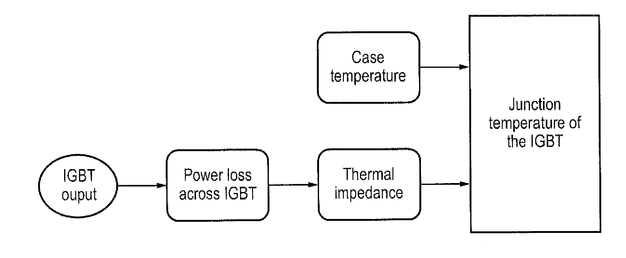
[0083]The thermal controller 100 receives signal inputs from sensors (not shown) that measure various operational parameters relating to the operation of the semiconductor switching device 150. These parameters include the case temperature of the switching device 150, the switching device collector-emitter voltage, the switching device supply current, and the switching frequency of the switching device 150.

[0084]The thermal controller 100 transmits a control signal to a gate control unit 160. The gate control unit 160 then transmits a drive signal to the switching device 150.

[0085]The control strategy of the thermal controller 100 ...


PUM


Abstract

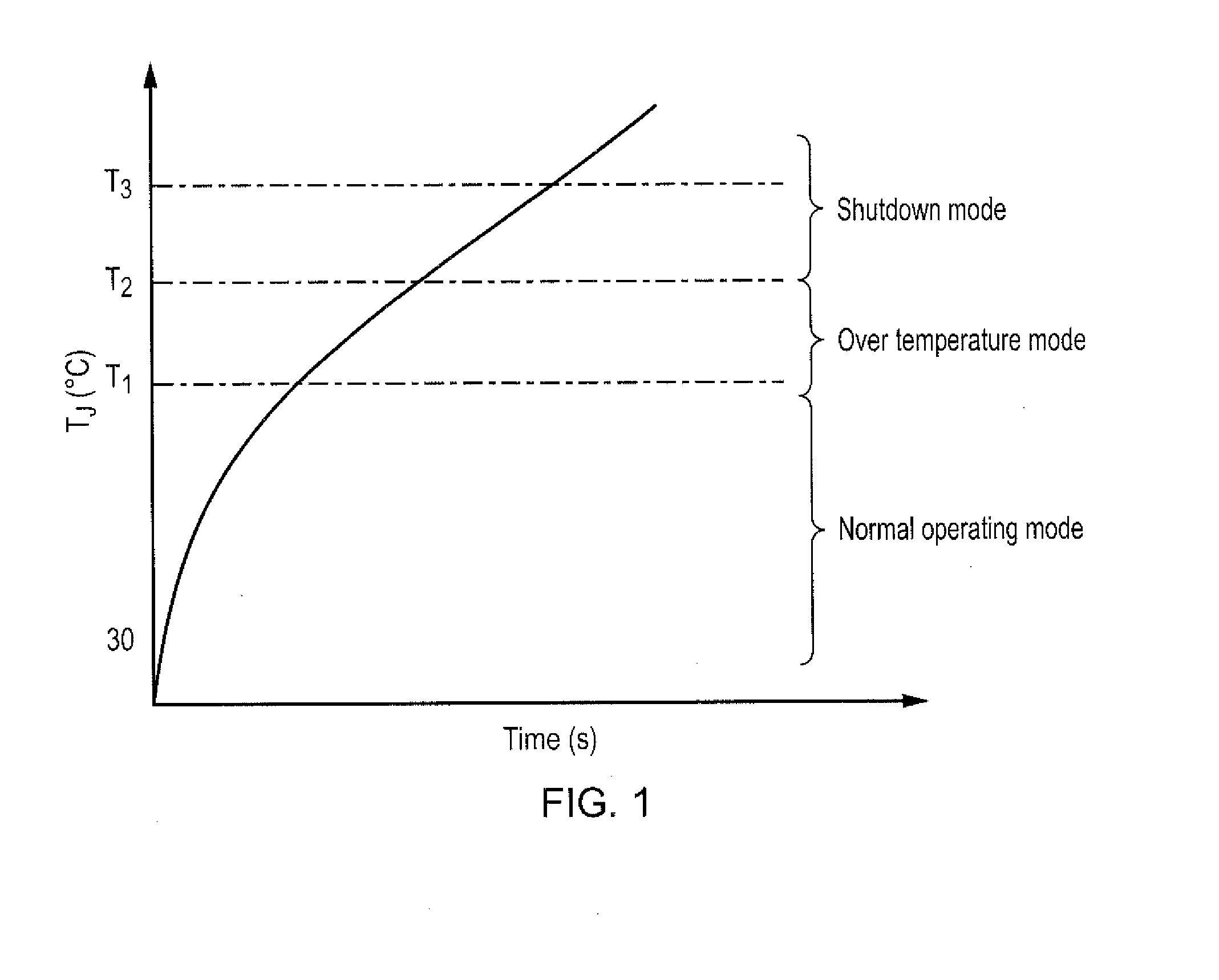
A thermal controller for driving a gate control unit of a gate-driven semiconductor switching device, the thermal controller comprising a junction temperature estimation module for generating an estimated junction temperature for the switching device, a gate voltage control module for modifying a gate voltage of the switching device, a switching frequency control module for modifying a switching frequency of the switching device, and a duty cycle control module for modifying the duty cycle of the switching device. In use, the thermal controller is adapted to activate one of the gate voltage control module, switching frequency control module and duty cycle control module dependent upon the estimated junction temperature in order to maintain the actual junction temperature below a pre-determined limit.

Description

[0001]This invention claims the benefit of UK Patent Application No. 1317490.9, filed on 3 Oct. 2013, and UK Patent Application No. 1302407.0 filed on 12 Feb. 2013, each of which is hereby incorporated herein in its entirety.FIELD OF THE INVENTION[0002]The present invention relates to a controller for an electrical switching device and particularly, but not exclusively, to a thermal controller for a semiconductor switching device.BACKGROUND TO THE INVENTION[0003]Many electrical loads ranging from laptop to high power motor drives are powered by power electronic converters using power switching devices such as Insulated Gate Bipolar Junction Transistors (IGBT) or Metal Oxide Substrate Field Effect Transistors (MOSFET). There is an increasing requirement to improve the reliability and availability of such electrical systems, in particular by the prevention of power switching device failures.[0004]Two common causes of power switching device failure are electrical faults and thermal str...

Claims


Application Information

Patent Timeline
Patent Type & Authority Applications(United States)
IPC IPC(8): H03K17/14
CPCH03K17/145H01L2924/0002
Inventor BHANGU, BIKRAMJITSATHIK, MOHAMED HALICK MOHAMEDNADARAJAN, SIVAKUMARGAJANAYAKE, CHANDANA JAYAMPATHI
Owner ROLLS ROYCE PLC
Learn More