Copper pillar full metal via electrical circuit structure

a full metal via and copper pillar technology, applied in the direction of electrical apparatus construction details, instruments, optical elements, etc., can solve the problems of carbon contamination, laser processing via structures can experience significant taper, and flexible circuits are expensive compared to some rigid pcb products, etc., to achieve attractive manufacturing cost and high density

Inactive Publication Date: 2014-08-14
HSIO TECH
View PDF20 Cites 48 Cited by
  • Summary
  • Abstract
  • Description
  • Claims
  • Application Information

AI Technical Summary

Benefits of technology

[0014]The present disclosure is directed to a high performance electrical interconnect that will enable next generation electrical performance. The present disclosure merges the long-term performance advantages of traditional PCB and semiconductor packagi

Problems solved by technology

In general, flexible circuits are expensive compared to some rigid PCB products.
Flexible circuits also have some limitations regarding layer count or feature registration, and are therefore generally only used for small or elongated applications.
Rigid PCBs and package substrates experience challenges as the feature sizes and line spacing are reduced to achieve further miniaturization and increased circuit d

Method used


Image

  • Copper pillar full metal via electrical circuit structure
  • Copper pillar full metal via electrical circuit structure
  • Copper pillar full metal via electrical circuit structure

Examples


Embodiment Construction

[0046]A high performance electrical interconnect according to the present disclosure may permit fine contact-to-contact spacing (pitch) on the order of less than 1.0 mm pitch, and more preferably a pitch of less than about 0.7 millimeter, and most preferably a pitch of less than about 0.4 millimeter. Such fine pitch high performance electrical interconnects are especially useful for communications, wireless, and memory devices.

[0047]The present high performance electrical interconnect can be configured as a low cost, high signal performance interconnect assembly, which has a low profile that is particularly useful for desktop and mobile PC applications. IC devices can be installed and uninstalled without the need to reflow solder. The solder-free electrical connection of the IC devices is environmentally friendly.

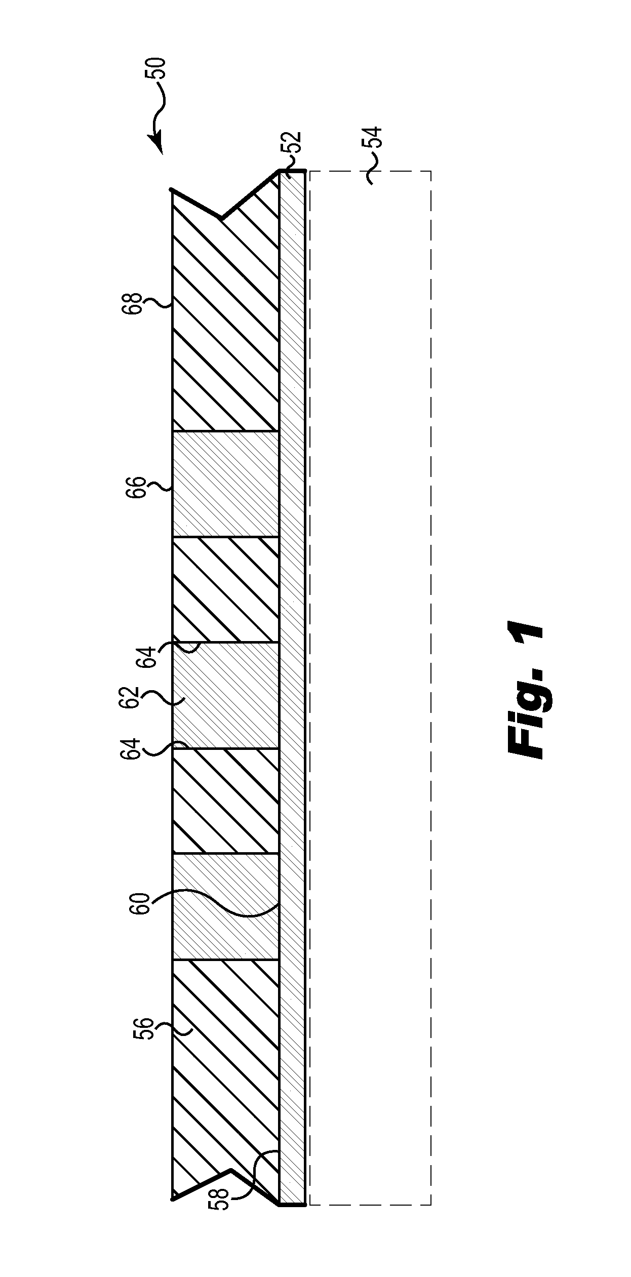
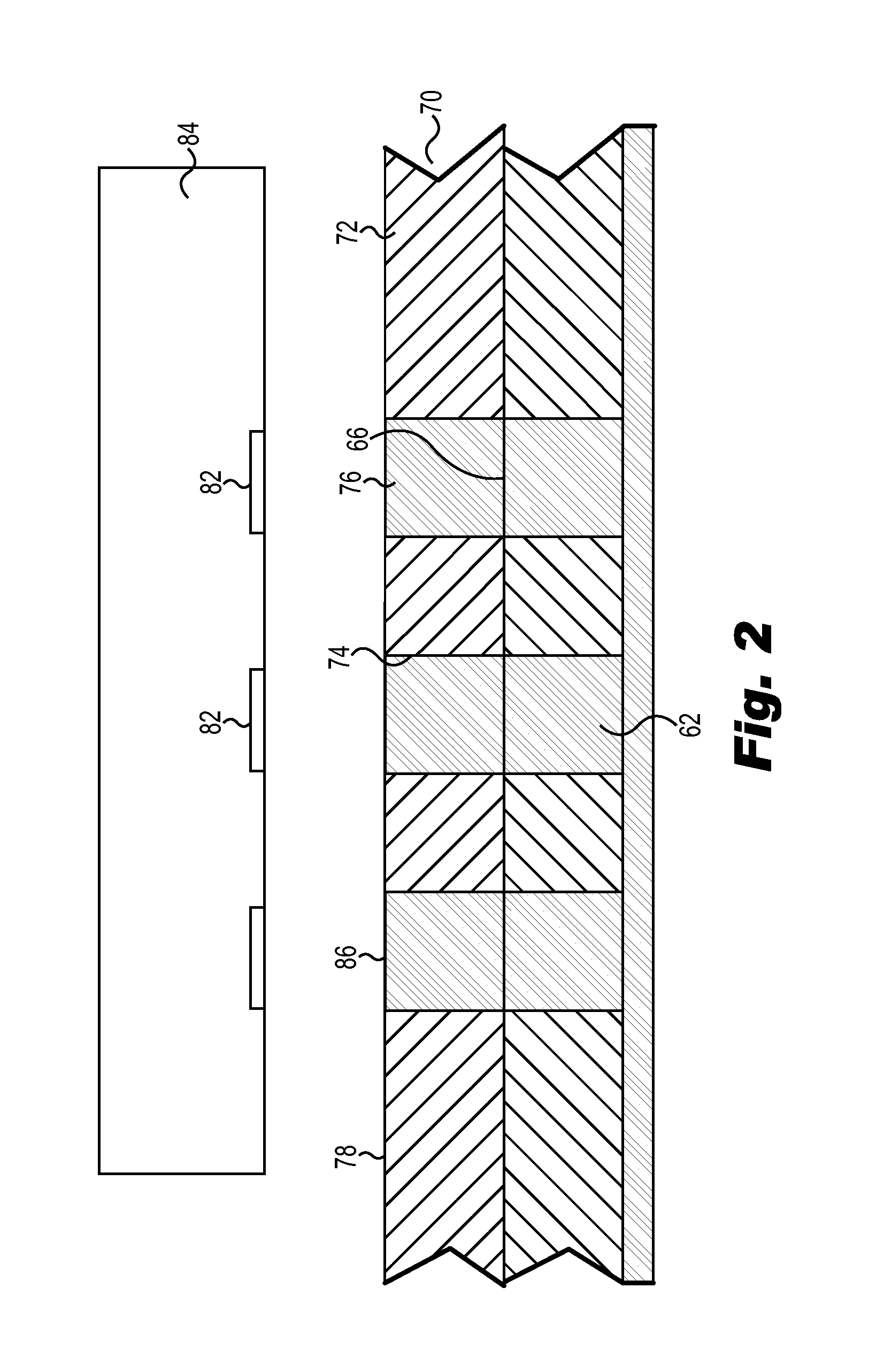
[0048]FIG. 1 is a side cross-sectional view of a method of making an electrical interconnect 50 using additive processes in accordance with an embodiment of the present dis...


PUM


Abstract

An electrical interconnect including a first circuitry layer with a first surface and a second surface. A first liquid dielectric layer is imaged directly on the first surface of the first circuitry layer to form a first dielectric layer with a plurality of first recesses. Conductive plating substantially fills a plurality of the first recesses to create a plurality of first solid copper conductive pillars electrically coupled to, and extending generally perpendicular to, the first circuitry layer. A second liquid dielectric layer is imaged directly on the first dielectric layer to form a second dielectric layer with a plurality of second recesses. Conductive plating substantially fills a plurality of the second recesses to form a plurality of second solid copper conductive pillars electrically coupled to, and extending parallel with, the first conductive pillars. An IC device is electrically coupled to a plurality of the second conductive pillars.

Description

CROSS-REFERENCE TO RELATED APPLICATIONS[0001]This application is a continuation-in-part of U.S. patent application Ser. No. 13 / 413,724 entitled Copper Pillar Full Metal Via Electrical Circuit Structure, filed Mar. 7, 2012, which claims the benefit of U.S. Provisional Application No. 61 / 451,685, filed Mar. 11, 2011, the disclosure of which is hereby incorporated by reference.[0002]This application is a continuation-in-part of U.S. patent application Ser. No. 13 / 266,573, titled COMPLIANT PRINTED CIRCUIT AREA ARRAY SEMICONDUCTOR DEVICE PACKAGE, filed Oct. 27, 2011, which is a national stage application under 35 U.S.C. §371 of International Application No. PCT / US2010 / 036363, titled COMPLIANT PRINTED CIRCUIT AREA ARRAY SEMICONDUCTOR DEVICE PACKAGE, filed May 27, 2010, which claims priority to U.S. Provisional Application No. 61 / 183,411, filed Jun. 2, 2009, all of which are hereby incorporated by reference in their entireties.[0003]This application is a continuation-in-part of U.S. patent...

Claims


Application Information

Patent Timeline
IPC IPC(8): H01L23/12H05K1/11H05K1/02H01L23/00
CPCH01L23/12H05K1/0298H05K1/11H01L24/17H01L2924/12044G02B6/3608G02B6/4281H01L23/3128H01L23/49822H01L23/49827H01L21/486H01L23/60H01L25/16H01L2223/6627H01L2224/16225H01L2224/48227H01L2924/09701H01L2924/3011H01L2924/3025H01L24/16H01L24/48H01L2224/16235H01L2224/48091H01L2224/48235H01L2224/81192H01L2924/00014H01L2924/15311H01L23/49816H01L23/49894H01L2924/1306H05K1/113H05K3/4644H05K2201/09563H05K2201/096H05K2203/0733H05K2203/1476H01L2224/08235H01L24/08H01L24/13H01L2224/1132H01L2224/131H01L2224/0401H01L2924/12042H01L2924/381H01L2924/00H01L2224/45099H01L2924/014
Inventor RATHBURN, JIM
Owner HSIO TECH
Why Eureka
Try Eureka