
Ion Detection

a mass analyser and ion detection technology, applied in the direction of instruments, particle separator tube details, optical radiation measurement, etc., can solve the problem of affecting the signal-to-noise ratio of the preamplifier output signal, and achieve the effect of reducing the capacitance and reducing the overall power spectral density of nois

Active Publication Date: 2014-08-14
THERMO FISHER SCI BREMEN
View PDF2 Cites 4 Cited by
  • Summary
  • Abstract
  • Description
  • Claims
  • Application Information

AI Technical Summary

Benefits of technology

The patent describes a detection arrangement that includes a compensation circuitry. The compensation circuitry provides a second compensation signal based on a second image current signal. This second compensation signal is used to improve the signal-to-noise ratio of the detection arrangement. The detection arrangement includes a preamplifier with a low output impedance. The second voltage buffer, which provides the second compensation signal, helps to reduce the capacitance between the detection electrodes and ground. Additionally, a shield is optionally included for each detection electrode to further reduce capacitance. The patent aims to improve the accuracy and sensitivity of the detection arrangement.

Problems solved by technology

However, when each compensation signal is applied, it compensates for the respective capacitance of the detection arrangement, affecting the signal-to-noise ratio of the preamplifier output signal.

Method used


Image

  • Ion Detection
  • Ion Detection
  • Ion Detection

Examples


first embodiment

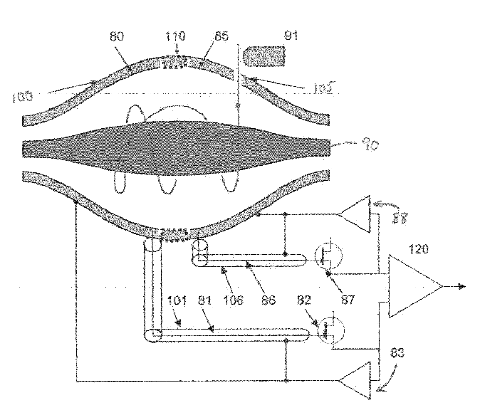
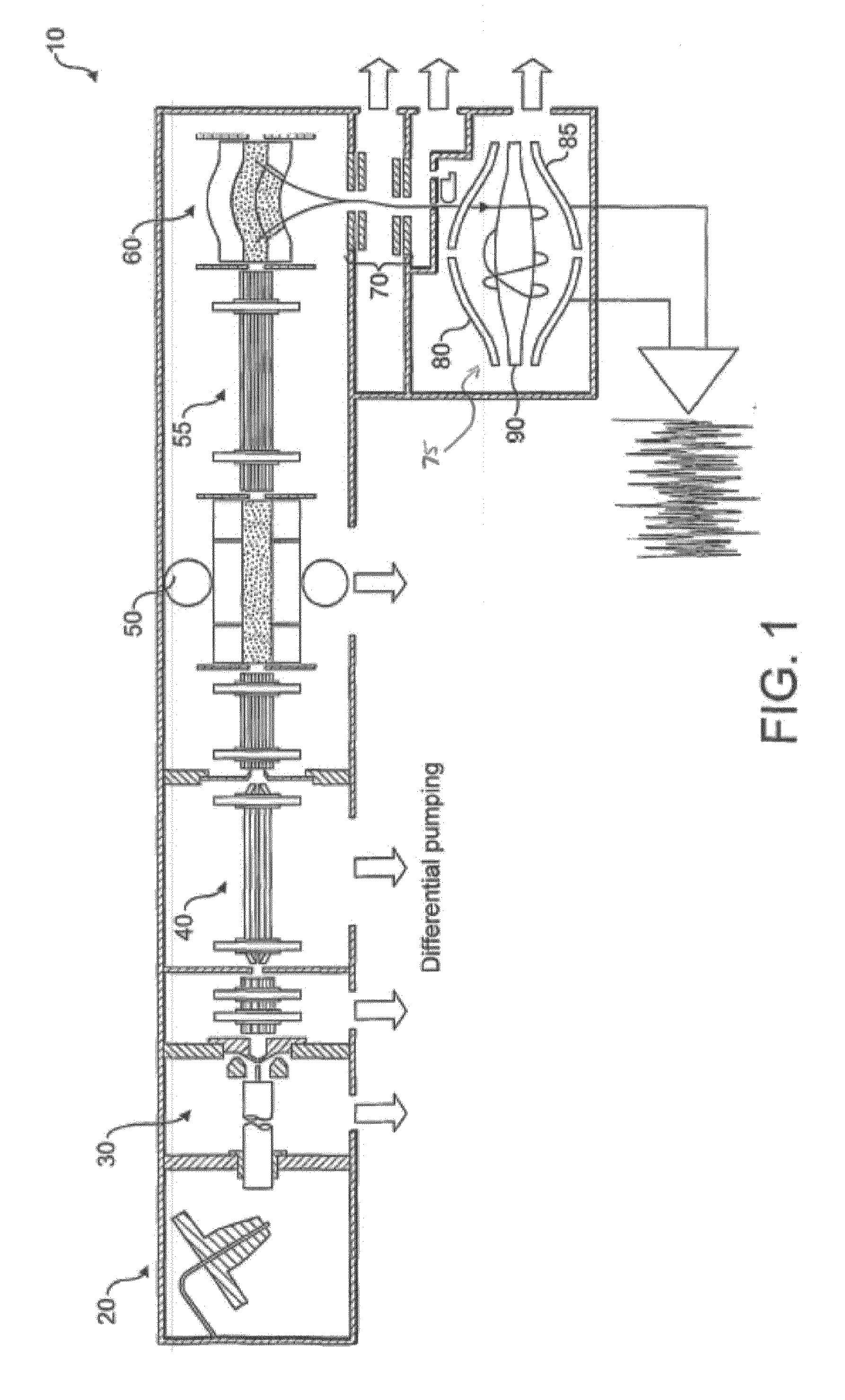
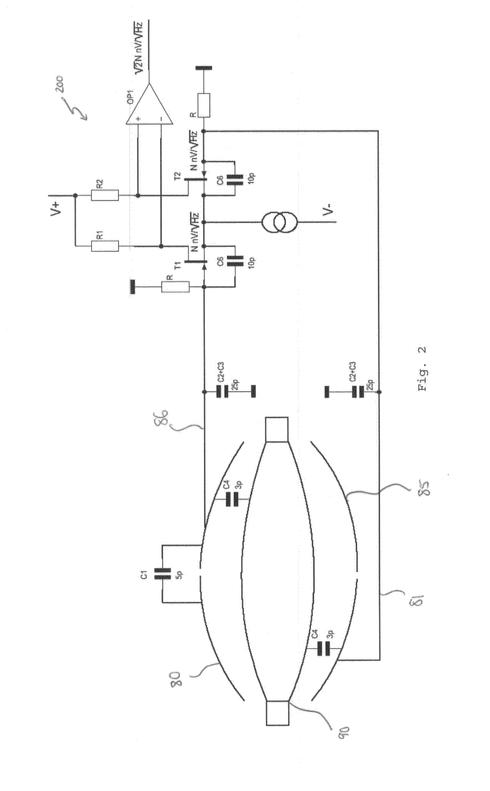
[0067]Referring next to FIG. 3, an ion detection arrangement according to the present invention is shown. The embodiment shown in FIG. 3 is based on that of FIG. 2, but with a number of significant changes. This embodiment exemplifies a way of detecting the image current signals. Features that are the same as those shown in FIG. 1 or 2 are identified by identical reference numerals.

[0068]In this case, outer electrodes 80 and 85 are made preferably from a clear or high-ohmic glass with a low temperature expansion coefficient. It is metallised (that is, metal coated) in such a way that the outer coating is not connected to the inner coating forming electrodes 80 and 85 but forms a first conductive surface 100 and a second conductive surface 105, each surrounding electrodes 80 and 85, correspondingly and thereby acting as shields. These surfaces 100, 105 could have a gap between them or, optionally, this gap could be covered by a high-ohmic resistive layer 110 (total resistance prefera...

second embodiment

[0078]Referring now to FIG. 5, there is shown a pre-amplifier according to the present invention for use with the ion detection arrangement of FIG. 4. The pre-amplifier 300 is similar to the pre-amplifier 120 shown in FIG. 4. However, it also includes additional features to compensate for the input capacitance of the pre-amplifier.

[0079]A signal with the same amplitude and phase as the input signal to the preamplifier from first detection electrode 80 is connected to the drain of the FET transistor T4 that is part of the first voltage follower 130. Similarly, a signal with the same amplitude and phase as the input signal to the preamplifier from second detection electrode 85 is connected to the drain of the FET transistor T3 that is part of the second voltage follower 135. This means that all three terminals of the transistor for each voltage follower have the same AC voltage and virtually no input capacitance between the terminals.

[0080]This is achieved by taking the signal applied...

third embodiment

[0082]Further reductions in capacitance can be achieved by means other than compensation. Referring next to FIG. 6, there is a shown an electrostatic trap mass analyzer according to the present invention. This shows the electrostatic orbital trapping-type of the mass analyzer shown in FIGS. 1 to 4, but with an additional feature. A conductor, here formed as a metal ring 140, is installed between the first detector electrode 80 and the second detector electrode 85. The gap between the metal ring 140 to each of electrodes is the same and the metal ring 140 is connected to voltage supply 145. The voltage supply 145 is preferably external.

[0083]Typically, a few hundred volts are applied to the metal ring 140 in order to get the field inside the mass analyser correct. This voltage is desirably static during detection, but could be switchable at other times. Preferably, this voltage has a ripple below a few (1, 2 or 3) millivolts and preferably within a frequency range below 100 to 200 kH...


PUM


Abstract

A mass analyser in which ions form packets that oscillate with a period has an ion detector comprising: a detection arrangement; and compensation circuitry. The detection arrangement may comprise: a plurality of detection electrodes detecting image current signals from ions in the mass analyser; and a preamplifier, providing an output based on the image current signals. The compensation circuitry provides a compensation signal to a respective compensatory part of the detection arrangement, based on one or more of the image current signals. A capacitance between each of the compensatory parts of the detection arrangement and a signal-carrying part of the detection arrangement affects the signal-to-noise ratio of the preamplifier output. A generator may provide a trapping field defining an ion trapping volume and a shielding conductor may be positioned between two detection electrodes, with a controller applying a voltage to the shielding conductor based on a detected image current.

Description

TECHNICAL FIELD OF THE INVENTION[0001]The present invention concerns ion detection for a mass analyser in which ions are caused to form ion packets that oscillate with a period, including a ion detector and a method of ion detection. Such a mass analyser may include an Fourier Transform Ion Cyclotron Resonance (FTICR) mass analyser, an electrostatic orbital trapping mass analyser or any other ion trap with image current detection.BACKGROUND TO THE INVENTION[0002]For Fourier Transform Mass Spectrometry (FTMS), the detection limit of mass-to-charge (m / z) ratio analysis has been defined in Marshall, A. G., Hendrickson C. L., “Fourier Transform Ion Cyclotron Resonance Detection: Principles and Experimental Configurations”, Int. J. Mass Spectrom. 2002, 215, 59-75. There, the detection limit is considered the minimum number of ions, M, of charge q detected with signal-to-noise ratio 3:1. This detection limit has been shown as proportional to the voltage noise of an input transistor of the...

Claims


Application Information

Patent Timeline
Patent Type & Authority Applications(United States)
IPC IPC(8): H01J49/02H01J49/00
CPCH01J49/0031H01J49/025H01J49/022H01J49/425H01J49/027H01J49/4245H01J49/02H01J49/42
Inventor KHOLOMEEV, ALEXANDERMAKAROV, ALEXANDER A.
Owner THERMO FISHER SCI BREMEN
Learn More