
Endoscope system and image generation method

an endoscope and image technology, applied in the field of endoscope systems and image generation methods, can solve the problems of weak auto-fluorescence used to detect hypertrophy, and achieve the effects of suppressing blood vessel display, and improving the visibility of irregularities on body tissu

Inactive Publication Date: 2014-08-07
FUJIFILM CORP
View PDF17 Cites 8 Cited by
  • Summary
  • Abstract
  • Description
  • Claims
  • Application Information

AI Technical Summary

Benefits of technology

The patent text describes a method for diagnosing cancer by analyzing patterns in a patient's body. While there are various methods for cancer diagnosis, the patent focuses on a method that uses both blood vessel patterns and irregular patterns for diagnosis. The technical effect of this method is to improve the visibility of the irregular pattern while reducing the visibility of the blood vessel pattern.

Problems solved by technology

However, auto-fluorescence used to detect the hypertrophy is weak.

Method used


Image

  • Endoscope system and image generation method
  • Endoscope system and image generation method
  • Endoscope system and image generation method

Examples


first embodiment

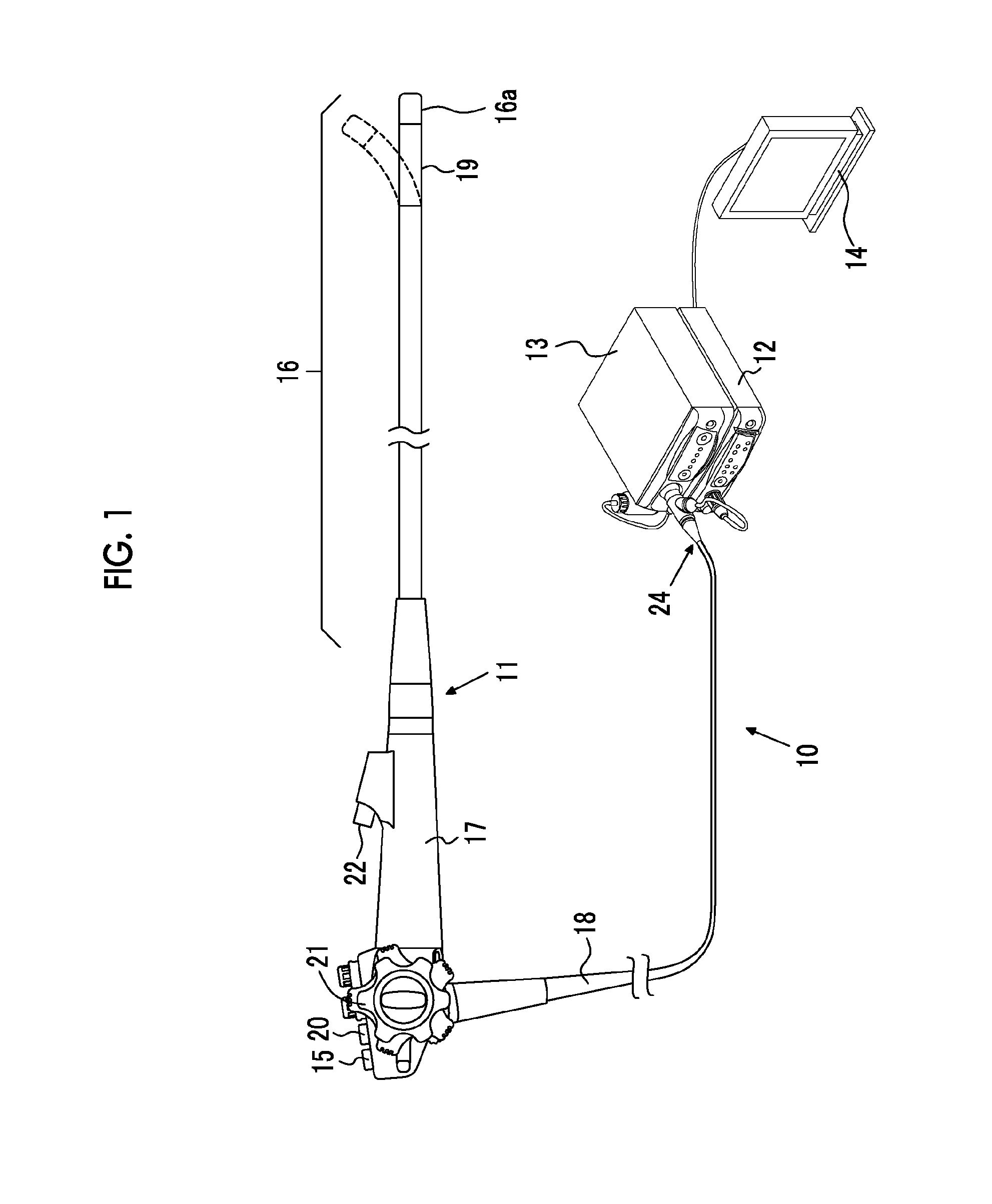
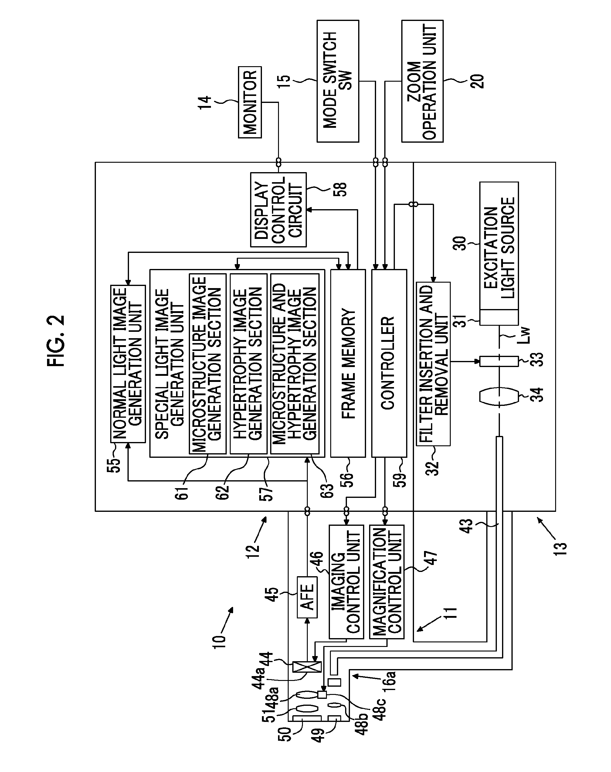
[0053]As shown in FIGS. 1 and 2, an endoscope system 10 of a first embodiment includes: an electronic endoscope 11 (a form of image signal acquisition unit) that images the inside of a subject; a processor device 12 that performs various kinds of image processing on the image captured by the electronic endoscope 11; a light source device 13 that supplies light for illuminating the subject to the electronic endoscope 11; and a monitor 14 that displays an image after various kinds of image processing are performed by the processor device 12.

[0054]The electronic endoscope 11 includes a flexible insertion unit 16 that is inserted into the subject, an operating unit 17 provided at the proximal end of the insertion unit 16, and a universal code 18 that makes a connection between the operating unit 17 and the processor device 12 and the light source device 13. A curved portion 19 obtained by connecting a plurality of curved pieces is formed at the distal end of the insertion unit 16. The c...

second embodiment

[0081]The light source device 113 includes an excitation light source 30, a phosphor 31, an RGB rotary filter 134, a filter insertion and removal unit 32, and a high absorption wavelength rejection filter 33. Also in the second embodiment, the white light W is generated by the excitation light source 30 and the phosphor 31. As shown in FIG. 14, the RGB rotary filter 134 has a disc shape, and is divided into three regions, each of which is a fan-shaped region having a central angle of 120°, in the circumferential direction, and a B filter portion 134b, a G filter portion 134g, and an R filter portion 134r are respectively provided in the three regions. The rotary filter 134 is rotatably provided so that the B filter portion 134a, the G filter portion 134b, and the R filter portion 134c are selectively inserted in the optical path Lw of the white light W.

[0082]As shown in FIG. 15, the B filter portion 134b has the same B transmission region as the B filter 44b of the CCD 44 in the fir...


PUM


Abstract

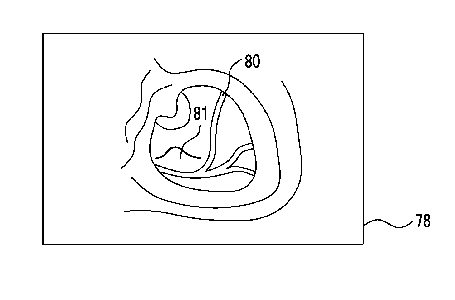
The visibility of irregularities on the body tissue, such as a superficial microstructure or hypertrophy, is improved. Excitation light EL is emitted to a phosphor to excite and emit white light W. High absorption wavelength cut light is generated by removing components in high absorption wavelength bands A1 and A2, in which the absorption coefficient of hemoglobin in the blood is high, from the white light using a high absorption wavelength rejection filter. The subject is illuminated with the high absorption wavelength cut light, and image light of the reflected light is captured by a color CCD. A microstructure image is generated based on a signal Bp output from the B pixel of the CCD. In this microstructure image, the display of superficial microvessels is suppressed. Accordingly, the visibility of superficial microstructures, such as a pit pattern, is relatively improved.

Description

Cross Reference to Related Applications:[0001]This application is a Continuation of PCT International Application No. PCT / JP2012 / 076291 filed on Oct. 11, 2012, which claims priority under 35 U.S C §119(a) to Patent Application No. 2011-225143 filed in Japan on Oct. 12, 2011 and Patent Application No. 2012-193908 filed in Japan on Sep. 4, 2012, all of which are hereby expressly incorporated by reference into the present application.BACKGROUND OF THE INVENTION[0002]1. Field of the Invention[0003]The present invention relates to an endoscope system capable of clearly observing a microstructure such as a pit pattern or an irregular pattern such as hypertrophy, which is formed on body tissue, and an image generation method[0004]2. Description of the Related Art[0005]In recent medical treatment, diagnosis or the like using an endoscope apparatus has been widely performed. In this endoscopic diagnosis, not only normal light observation, in which white light of broadband light is used as il...

Claims


Application Information

Patent Timeline
Patent Type & Authority Applications(United States)
IPC IPC(8): A61B1/00A61B1/06
CPCA61B1/0661A61B1/00009A61B1/0051A61B1/0638A61B1/0684A61B5/0084A61B1/0646F04C2270/041A61B1/0653A61B1/000094
Inventor YAMAGUCHI, HIROSHIOZAWA, SATOSHIIIDA, TAKAYUKI
Owner FUJIFILM CORP
Learn More