
Memory device using spin hall effect and methods of manufacturing and operating the memory device

a memory device and hall effect technology, applied in the field of memory devices, can solve problems such as leakage current flows and errors during read operations

Active Publication Date: 2014-07-31
SAMSUNG ELECTRONICS CO LTD
View PDF3 Cites 29 Cited by
  • Summary
  • Abstract
  • Description
  • Claims
  • Application Information

AI Technical Summary

Benefits of technology

The patent describes memory devices that have smaller cells, do not interfere with adjacent cells, can perform multiple writing, and use a spin hall effect. These devices have a stable operation and may be designed independently of the performance and size of the cell transistor. Furthermore, these devices have increased performance as a result of the transistor being located on the outside of the cell region, allowing for greater current application. Additionally, the cross point device overcomes an operational limitation of the related art with its ability to perform multi writing, resulting in a high-speed memory device.

Problems solved by technology

In addition, when the unit cell is a cross point device, leakage current flows to an adjacent cell during a read operation.
Thus, because a resistance value of a unit cell to be actually read cannot be accurately measured, errors may occur during the read operation.

Method used


Image

  • Memory device using spin hall effect and methods of manufacturing and operating the memory device
  • Memory device using spin hall effect and methods of manufacturing and operating the memory device
  • Memory device using spin hall effect and methods of manufacturing and operating the memory device

Examples


Embodiment Construction

[0040]Various example embodiments will now be described more fully with reference to the accompanying drawings in which some example embodiments are shown. However, specific structural and functional details disclosed herein are merely representative for purposes of describing example embodiments. Thus, the invention may be embodied in many alternate forms and should not be construed as limited to only example embodiments set forth herein. Therefore, it should be understood that there is no intent to limit example embodiments to the particular forms disclosed, but on the contrary, example embodiments are to cover all modifications, equivalents, and alternatives falling within the scope.

[0041]In the drawings, the thicknesses of layers and regions may be exaggerated for clarity, and like numbers refer to like elements throughout the description of the figures.

[0042]Although the terms first, second, etc. may be used herein to describe various elements, these elements should not be limi...


PUM


Abstract

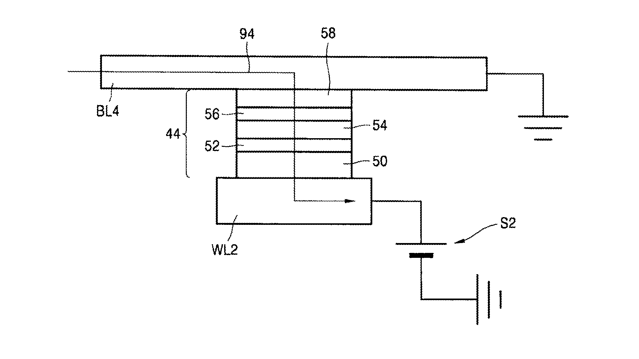
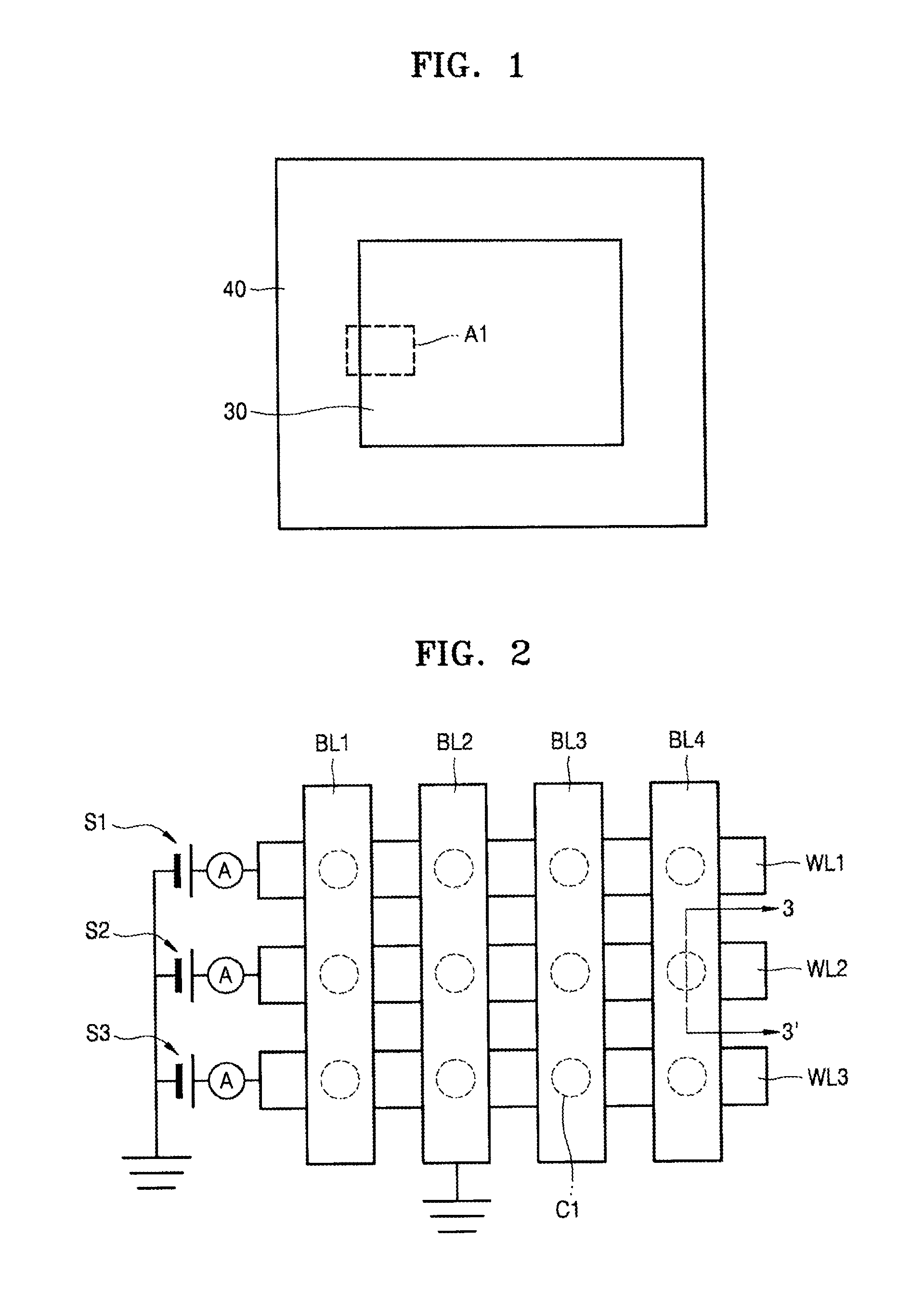
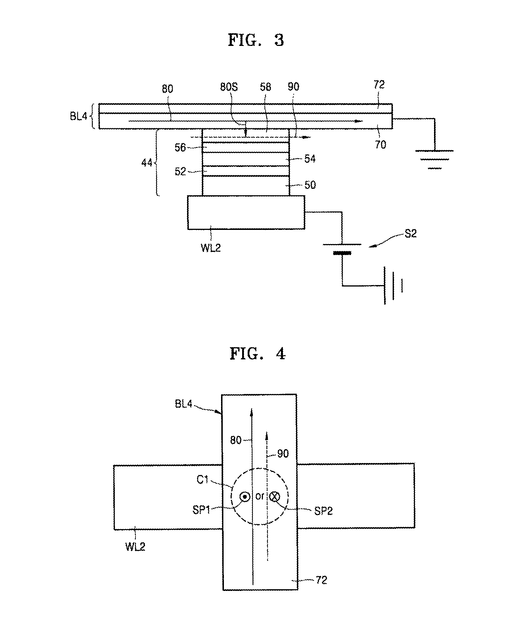
A memory device using a spin hall effect, and methods of manufacturing and operating the memory device, include applying a first operational current to a bit line of the memory device such that a spin current is applied to a magnetic tunnel junction (MTJ) cell coupled to the bit line due to a material in the bit line, wherein the bit line is electrically connected to a word line via the MTJ cell, and the word line intersects the bit line.

Description

CROSS-REFERENCE TO RELATED APPLICATIONS[0001]This application claims the benefit of priority under 35 U.S.C. §119 from Korean Patent Application No. 10-2013-0008630, filed on Jan. 25, 2013, in the Korean Intellectual Property Office, the disclosure of which is herein incorporated by reference in its entirety.BACKGROUND[0002]1. Field[0003]Example embodiments relate to memory devices, and more particularly, to memory devices using a spin hall effect and / or methods of manufacturing and operating the memory device.[0004]2. Description of the Related Art[0005]In general spin transfer torque magnetic random access memories (STT-MRAMs), a transistor is formed in each cell in order to minimize interference between the cell and a peripheral cell. Thus, each cell has a structure in which one transistor and one capacitor are formed, that is, a 1T-1C structure. Accordingly, the size of each cell is 6 F2 or more.[0006]As the need for high integration of semiconductor devices increases, research ...

Claims


Application Information

Patent Timeline
Patent Type & Authority Applications(United States)
IPC IPC(8): G11C11/16H01L43/02H10B69/00
CPCG11C11/1673G11C11/1675G11C11/18H01L27/222G11C11/161H01L43/08G11C11/1659H10B61/00H10N50/80H10N50/10G11C11/16H10N50/01
Inventor PI, UNG-HWANKIM, KWANG-SEOKKIM, KEE-WONLEE, SUNG-CHULJANG, YOUNG-MAN
Owner SAMSUNG ELECTRONICS CO LTD
Learn More