Testing apparatus for a high speed communications jack and methods of operating the same

a communication jack and high-speed technology, applied in the direction of coupling device connection, transmission monitoring, instruments, etc., can solve the problems of signal failure, design of such physical components is plagued by a lack of understanding of what, and still speed limited by the current design of certain physical components

Active Publication Date: 2014-07-24
SENTINEL CONNECTOR SYST
View PDF70 Cites 0 Cited by
  • Summary
  • Abstract
  • Description
  • Claims
  • Application Information

AI Technical Summary

Benefits of technology

The present invention relates to a testing unit for high speed communication jacks, which includes a substrate with vias, pin traces, end traces, branch traces, and traces. The distance between the traces and the grounding plane is adjusted to magnetically couple them. The inductance and capacitance of each trace are adjusted to magnetically couple them. The height and width of the traces and the distance between them are adjusted to match the capacitance of each other. The testing unit also includes a second ground plane and a connection unit for transmitting signals. The invention allows for efficient testing of high speed communication jacks.

Problems solved by technology

However, even as more recent versions of various standards provide for theoretically higher data rates or speeds, they are still speed limited by the current designs of certain physical components.
Unfortunately, the design of such physical components is plagued by a lack of understanding of what is necessary to achieve consistent signal quality at multi-gigahertz and higher frequencies.
If not, a load with one impedance value will reflect or echo part of a signal being carried by a cable with a different impedance level, causing signal failures.
The RJ45 jack is also a significant component in nearly every communications circuit, however, jack manufacturers have not provided the same level of attention to its performance.
Thus, although problems related to existing RJ45 jacks are well documented in tests and their negative impact on high frequency signal lines is understood, the industry seems reluctant to address the issues for this important component of the physical layer.

Method used


Image

  • Testing apparatus for a high speed communications jack and methods of operating the same
  • Testing apparatus for a high speed communications jack and methods of operating the same
  • Testing apparatus for a high speed communications jack and methods of operating the same

Examples


Embodiment Construction

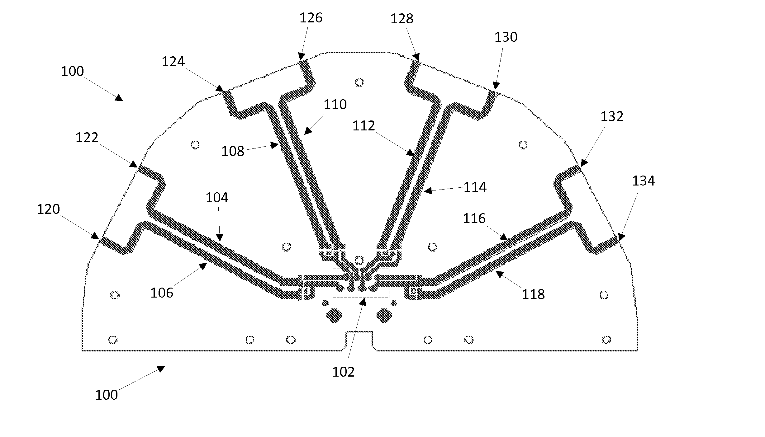
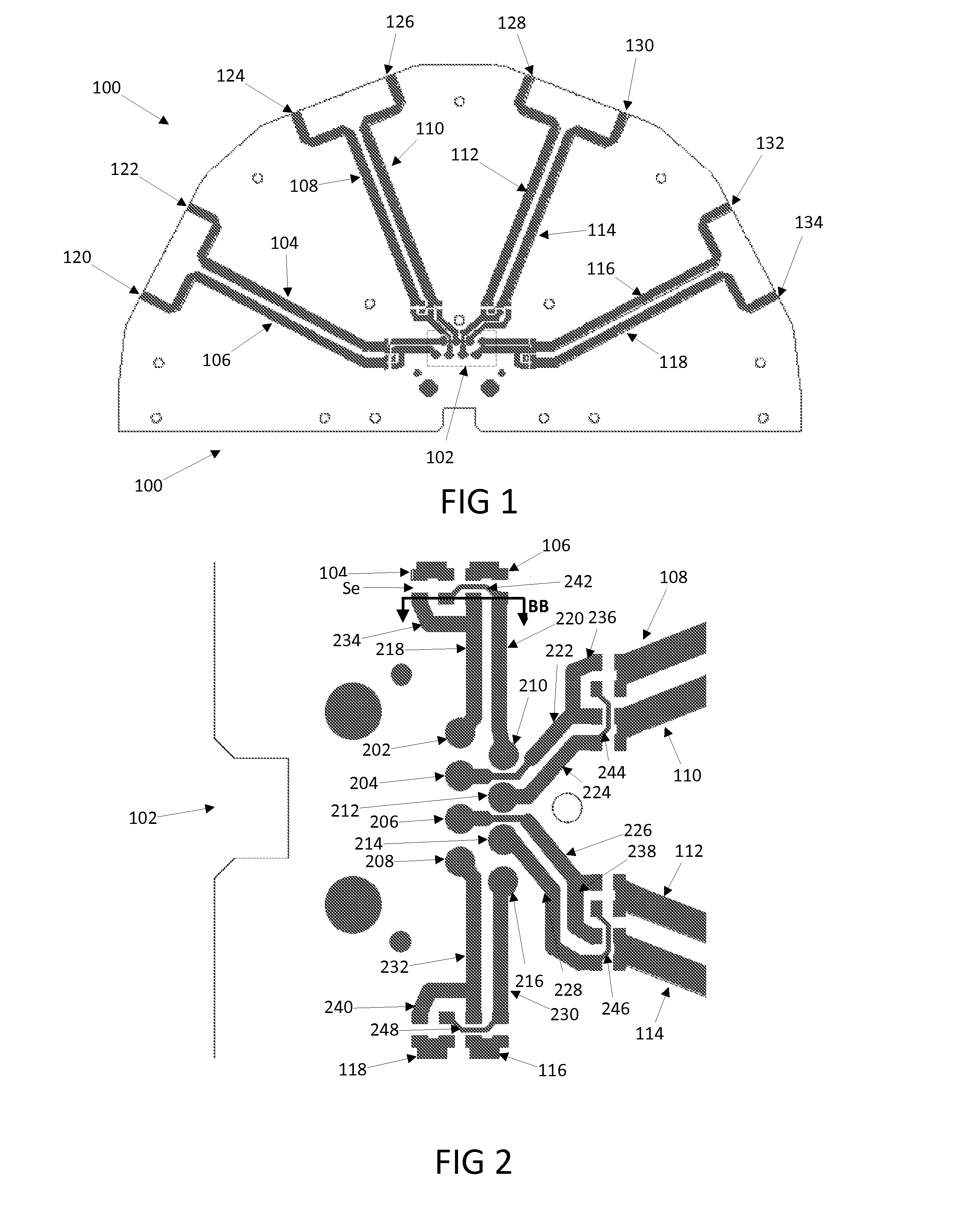
[0036]FIG. 1 illustrates a testing unit 100 for a high speed communication jack. The testing unit 100, or testing framework, includes a pin connection portion 102 that is configured to affix to a high speed communication jack such as, but not limited to, a RJ 45 communication jack. Traces 104, 106, 108, 110, 112, 114, 116 and 118 extend radially from the pin connection portion 102 to the outer edge of the testing unit 100. The end of each trace 104, 106, 108, 110112, 114, 116 and 118 terminates at the edge of the testing unit 100 to allow for the connection of a communication unit (not shown). The connection units 120, 122, 124, 126, 128, 130, 132 and 134 may be any type of connector including, but not limited to a RJ 45 connector.

[0037]FIG. 2 depicts a blown up view of the connection portion 102. The connection portion 102 includes vias 202, 204, 206, 208, 210, 212, 214, and 216 that are sized to engage the pins of a high speed communication jack. Pin traces 218, 220, 222, 224, 226...


PUM

PropertyMeasurementUnit
Capacitanceaaaaaaaaaa
Lengthaaaaaaaaaa

Abstract

A testing unit including a substrate, a plurality of vias located in the substrate, a plurality of pin traces having a height and a width and each extending from a respective via towards an edge of the substrate, a plurality of end traces having a height and a width with each end trace extending from an end of a respective pin trace towards the edge of the substrate, a plurality of branch traces having a height and a width and each extending from a side of a respective pin trace, a plurality of traces extending from the end of a respective end trace, branch trace or pin trace to the edge of the substrate, where each end trace is adjacent to a respective branch trace, each end trace is adjacent to a respective branch trace on one side and a pin trace on the opposite side, and each pin trace is adjacent to another pin trace on one side.

Description

CROSS REFERENCE TO RELATED APPLICATIONS[0001]This application is a continuation in part of U.S. patent application Ser. No. 13 / 739,214, filed Jan. 11, 2013, which is incorporated by reference herein in its entirety.FIELD OF THE DISCLOSURE[0002]The present disclosure relates to a testing framework of a network connection jack used to connect a network cable to a device.BACKGROUND OF THE DISCLOSURE[0003]As electrical communication devices and their associated applications become more sophisticated and powerful, their ability to gather and share information with other devices also becomes more important. The proliferation of these intelligent, inter networked devices has resulted in a need for increasing data throughput capacity on the networks to which they are connected to provide the improved data rates necessary to satisfy this demand. As a result, existing communication protocol standards are constantly improved or new ones created. Nearly all of these standards require or signifi...

Claims


Application Information

Patent Timeline
IPC IPC(8): H04L1/24H04B17/00
CPCH04B17/00H04L1/24G01R1/0416H01R13/6469H01R13/6474H01R24/64H05K1/025H05K1/0268H05K1/0366H05K2201/09027H05K2201/10189
Inventor ROBINSON, BRETT D.
Owner SENTINEL CONNECTOR SYST
Why Eureka
Try Eureka