Optical Fiber Cable Installation in a Pressure Sewerage

Active Publication Date: 2014-07-24
JELCER IP
View PDF5 Cites 33 Cited by
  • Summary
  • Abstract
  • Description
  • Claims
  • Application Information

AI Technical Summary

Benefits of technology

The patent is about a device that can protect cables from damage when they are being installed underground. The device has a part that can be rotated to a protected position to keep the cables safe from damage. Additionally, the device has a part that can hold a sensor or other instrument, which can be used to measure things like temperature or gas concentrations. This part is designed to protect the sensor from damage as well.

Problems solved by technology

This causes too little flow in a normal sewer for the purpose of draining the sewer content.
As a result it is not possible to introduce a robot into an existing pressure sewer for the purpose of laying a glass fibre cable.
Nor is it possible to simply open the pressure sewer in order to make a connection.
It is further not possible to draw the glass fibre cable to a dwelling via a house connection of the sewer, but a bridging is necessary between a connection point in the pressure sewer and a further connection to the dwelling, such as for instance an inspection well.
It is however a drawback of the known medium conduit that the cable is situated inside the medium conduit at a position which cannot be determined.
When the medium conduit transports something other than gas or liquid, such as in particular a pressure sewer, this can easily result in highly undesirable blockages.
Not only must a blockage be cleared as quickly as possible, a blockage is also difficult to trace since the conduit is located under the ground and is optically non-transparent.

Method used


Image

  • Optical Fiber Cable Installation in a Pressure Sewerage
  • Optical Fiber Cable Installation in a Pressure Sewerage
  • Optical Fiber Cable Installation in a Pressure Sewerage

Examples


Embodiment Construction

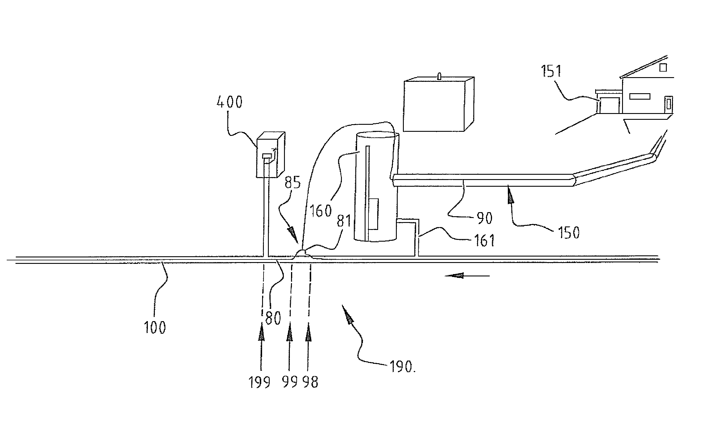
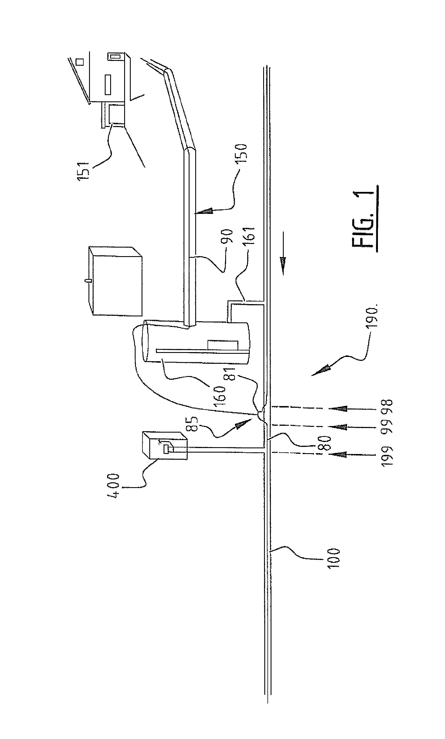
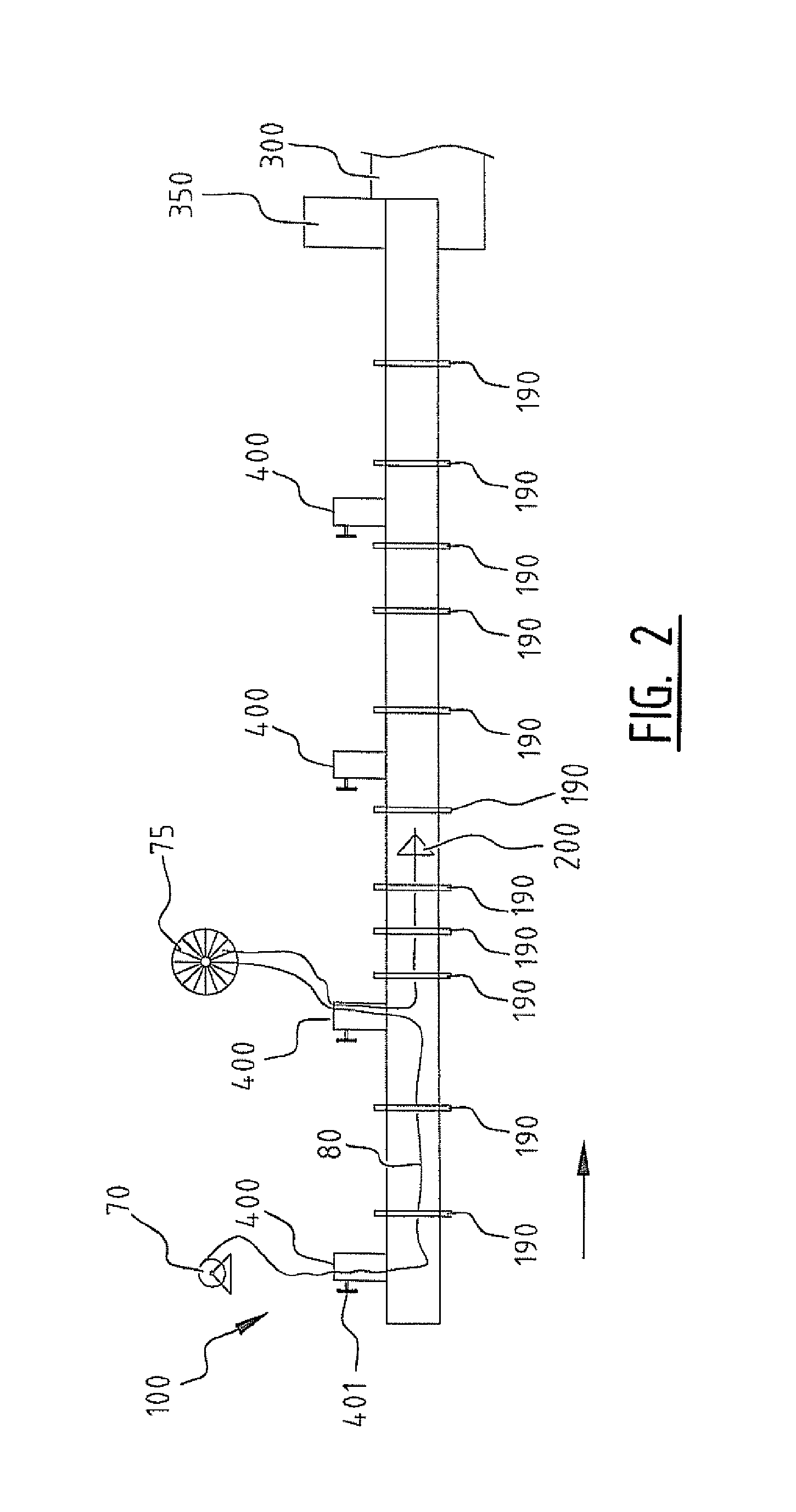
[0056]The figures are of schematic nature. Components are not shown to scale. The same or similar elements are designated in different figures with corresponding reference numerals.

[0057]FIG. 1 is a schematic view of a house connection 190 to medium conduit 100 according to the invention. In this embodiment medium conduit 100 is a pressure sewer. Not otherwise precluded is that the invention is applied to another type of medium conduit, such as a water conduit, a district heating system based on conduits with hot water or hot air, a gas conduit. The medium conduit is suitable for transporting a medium using pressure, wherein it is not necessary for the pressure to be continuously present; pressure sewers are for instance usually operated by a number of pumps which are only activated at regular or irregular times. The terms ‘pressure sewer’ and ‘medium conduit’ will be used interchangeably. The medium flows in the medium conduit in the direction indicated by the arrow. The initial pu...


PUM


Abstract

A house connection for a cable in a medium conduit comprises a cable passage with which the cable is taken out of the medium conduit. The cable passage is provided with a cable tensioner with which a portion of the cable can be tensioned in the medium conduit. The cable passage is preferably part of a rotatable manifold.

Description

FIELD OF THE INVENTION[0001]The invention relates to the laying of a cable in a medium conduit. The invention also relates to a thus obtained medium conduit provided with a cable. The invention further relates to auxiliary means for use herein.BACKGROUND OF THE INVENTION[0002]Cables for telecommunication, such as glass fibre cables in particular, are seen as the basis of a communication network. Efficiency requires that use be made of already existing pipe systems in the ground for the purpose of laying such a new cable network. A sewer forms a very suitable pipe network here. The sewer system in cities comprises a network of main sewers running below streets to which individual house sewers or house sewer connections are connected. The main sewer has a cross-section sufficiently large for a robot, and there are sewer drains through which a glass fibre cable can be introduced into the sewer. A method for laying a glass fibre cable in such a main sewer is per se known from EP 1868020...

Claims


Application Information

Patent Timeline
IPC IPC(8): F16L9/18H02G1/06
CPCG02B6/4464G02B6/4465H02G1/08F16L9/18H02G1/06G02B6/545G02B6/52G02B6/4459G02B6/502
Inventor SPIJKER, JOHANNES GERHARDUS
Owner JELCER IP
Why Eureka
Try Eureka