
Method of making nanaofluids for ground souce heat pumps and other applications

Inactive Publication Date: 2014-07-17
ACTA TECH
View PDF9 Cites 4 Cited by
  • Summary
  • Abstract
  • Description
  • Claims
  • Application Information

AI Technical Summary

Benefits of technology

The invention allows nanoparticles to enter the heat pump's circulating loop, which improves heat transfer in the base fluid. This results in the creation of a nanofluid that is used in GHPs.

Problems solved by technology

GHPs are a proven technology and savings in the range of 30 to 60 percent have been documented, but the greatest barrier to acceptance of GHPs in the marketplace is their high initial cost and long payback period.
This approach produces an undesirable increase in the sizes of the heat exchange device and a larger circulation loop.
In addition, the inherent poor thermodynamic properties of conventional heat transfer fluid (ethylene or propylene glycol) limits the amount of heat transfers.
Unfortunately, when this has been tried, large size particles follow Maxwell's theory in that they lack stability and settle out of the liquid.
The suspension also causes additional flow resistance and possible erosion problems which are negative effects of using a mixture of a base liquid with suspended large metallic particles.
Over time it has been recognized that thermal conductivity is not the best figure of merit to evaluate nanofluids because the nanoparticles tend to increase the viscosity of the nanofluid.
It has been recognized that thermal conductivity of the nanofluid is not a good indicator of heat transfer performance of a fluid.
Ethylene glycol is a hazardous material that might be consumed by people should the ethylene glycol get into the drinking water because of a leak in the bore field or pond or through leaks in the fittings and seals of the circulating loop system.

Method used


Image

  • Method of making nanaofluids for ground souce heat pumps and other applications
  • Method of making nanaofluids for ground souce heat pumps and other applications
  • Method of making nanaofluids for ground souce heat pumps and other applications

Examples


Embodiment Construction

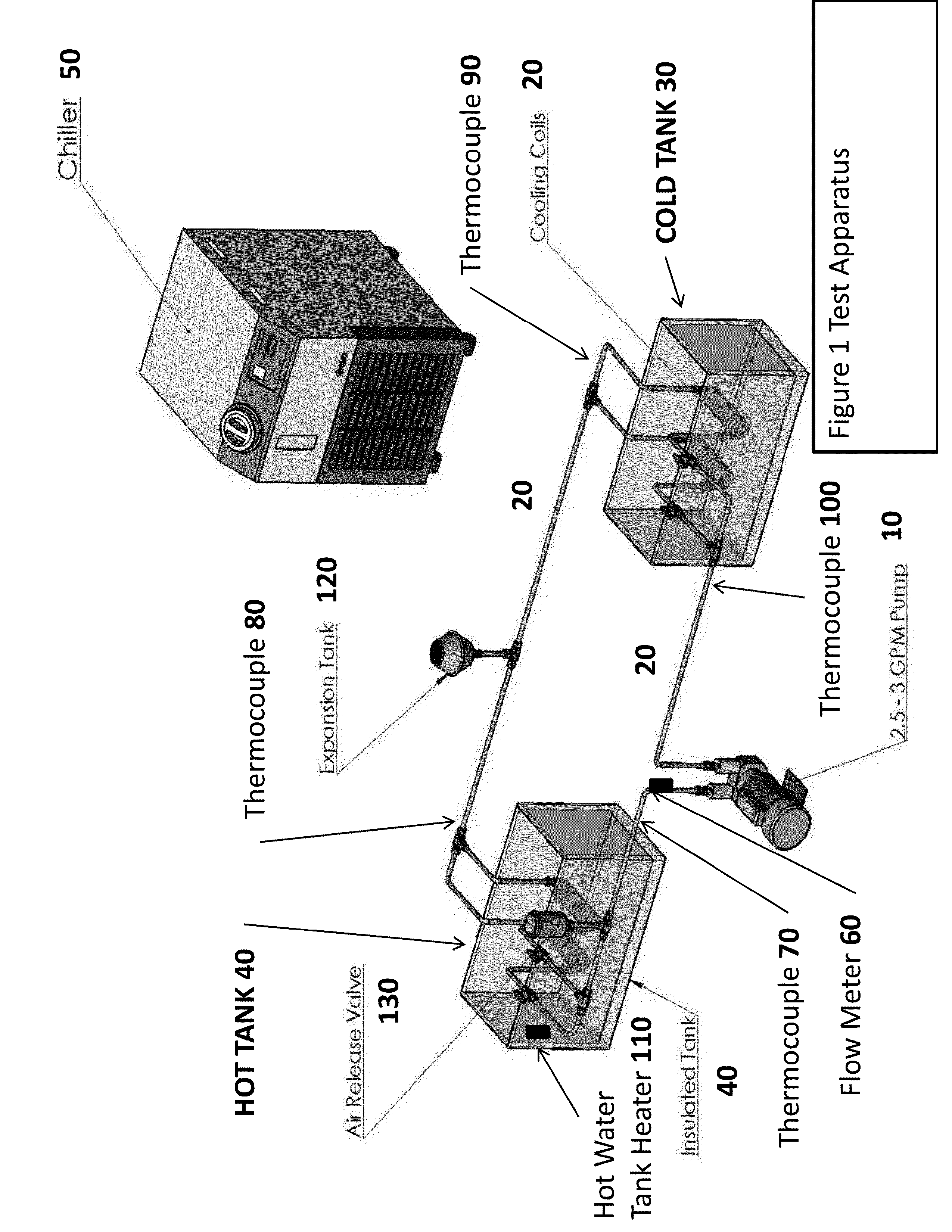
[0030]FIG. 1 illustrates a test apparatus for testing circulating fluids to be used in GHP. The circulating loop 20 connects the bore field or the pond to the heat pump's condenser in GHPs. A constant speed, two-speed or variable speed pump 10 circulates the circulation fluid usually propylene or ethylene glycol in the loop 20. The invention is a new type of nanofluid to be used in the loop 20 that increase the heat transfer. The test apparatus models a typical heat pump and has a cold tank 30 and hot tank 40. A chiller 50 can be used in the cold tank to maintain near isothermal temperatures in the cold tank 30. The goal is to create a heat transfer environment similar to ground source heat pump, where 85 F loop circulating fluid leaves the heat pump and enters the ground loop or pond loop. In the test apparatus the hot tank 40 presents the condenser of the GHP and the cold tank 30 represents the bore field or pond. In this test apparatus the water temperature in the cold tank 30 is...


PUM


Abstract

A method on making a nanofluid using nanoparticles without the use of a surfactant to hold the nanoparticles in suspension.

Description

STATEMENT REGARDING FEDERALLY SPONSORED RESEARCH OR DEVELOPMENT[0001]Research was partially funded under US Environmental Protection Agency Contract EPA-EP-D-11-034. The title of the contract is “A Greener and More Energy Efficient Renewable Energy Resource—Ground Source Heat Pumps.”REFERENCE TO RELATED APPLICATIONS[0002]N / ABACKGROUND OF THE INVENTION[0003]Conventional geothermal heat pumps (GHPs) have the potential to provide significant energy savings over typical air-source heat pumps or typical furnaces with air conditioners. GHPs are a proven technology and savings in the range of 30 to 60 percent have been documented, but the greatest barrier to acceptance of GHPs in the marketplace is their high initial cost and long payback period.[0004]This invention uses nanofluid in the circulation loop of a GHP that will increase the heat transfer; thereby reducing the installation cost and reduce the operating cost of GHPs. Improved heat transfer will lower the installation cost because...

Claims


Application Information

Patent Timeline
IPC IPC(8): C09K5/10
CPCC09K5/10B82Y30/00
Inventor OLSON, JOHN MELVIN
Owner ACTA TECH
Learn More