Systems And Methods For Providing Optical Signals Through A RF Channel Of A Rotary Coupler

a technology of optical signals and rotary couplers, which is applied in the direction of optical elements, waveguide devices, instruments, etc., can solve the problems of potential emi (electromagnetic interference) concerns in high-power rf applications, and the inability to support a large number of circuits required to support the electronic bus architecture,

Active Publication Date: 2014-07-10
L3 TECH INC
View PDF2 Cites 0 Cited by
  • Summary
  • Abstract
  • Description
  • Claims
  • Application Information

AI Technical Summary

Benefits of technology

[0011]In one exemplary embodiment, a rotary coupler may be provided with an optical transmission line (e.g., a single or multiple mode fiber optic line) that passes inside or through the center of an inner conductor of a coaxial RF transmission line that itself extends across the rotational interface / s of the rotary coupler. In such an embodiment, both the optical transmission line and the RF transmission line may be positioned at, or close to, the axis of rotation of the rotary coupler. In a further embodiment, a rotary coupler may be provided that is configured to transfer optical signals and multiple RF channels across the rotational interface / s of a rotary coupler. In another exemplary embodiment, a rotary coupler may be configured to transfer optical and RF energy across rotational interface / s of the rotary coupler using an optical rotary joint positioned inside the inner conductor of a first RF channel transmission line that itself is substantially centered at, and in line with, the rotational axis of the rotary coupler. When integrated inside or within an on-axis RF transmission line of a rotary coupler, an optical transmission line may advantageously provide on-axis optical signal communication through the rotary coupler without adversely impacting or affecting the on-axis RF signal transmissions through the rotary coupler. In a further embodiment, the optical rotary joint may be positioned adjacent to a stepped impedance choke that is provided between the fixed and rotating portions of the inner conductor of the first RF channel transmission line.

Problems solved by technology

Some draw-backs with this technology include the potential for a large number of circuits required to support the electronic bus architecture, potential bandwidth limitations in passing data across a multi-circuit slip ring assembly and potential EMI (electromagnetic interference) concerns in high power RF applications.
It is also not uncommon for certain applications, such as airborne installations, to have physical packaging constraints which will limit the available volume for a slip ring installation which could limit system capability.

Method used


Image

  • Systems And Methods For Providing Optical Signals Through A RF Channel Of A Rotary Coupler
  • Systems And Methods For Providing Optical Signals Through A RF Channel Of A Rotary Coupler
  • Systems And Methods For Providing Optical Signals Through A RF Channel Of A Rotary Coupler

Examples


Embodiment Construction

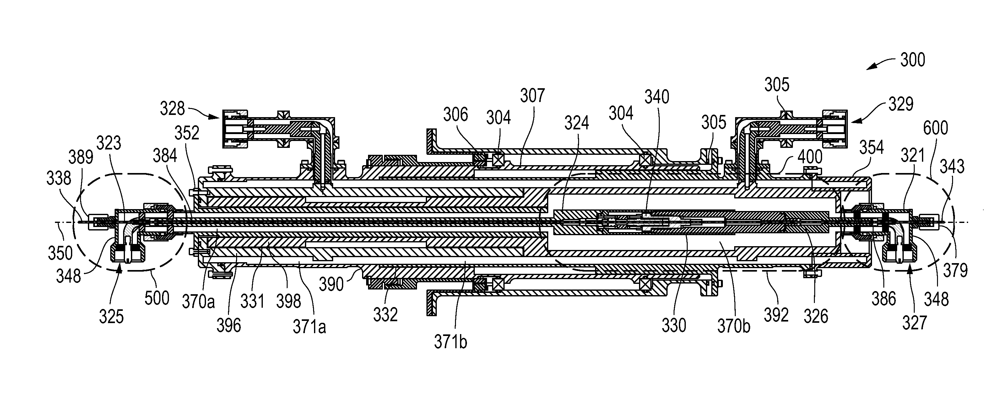
[0030]FIG. 3 is a cross sectional view of a combined multiple channel (in this example dual-channel) radio frequency (RF) and optical rotary coupler assembly 300 according to one exemplary embodiment of the disclosed systems and methods. For further reference, FIG. 9 is an outer perspective view of the optical rotary coupler assembly 300 of FIG. 3. In the illustrated embodiment FIG. 3, rotary coupler 300 has a stator portion 352 and a mating rotor portion 354, and is configured to transmit an optical signal channel and two RF signal channels (referred to herein as RF channels 1 and 2) in a direction substantially parallel with the longitudinal axis 350 of rotary coupler 300, and across rotational interface / s that are formed between mating stator portion 352 and rotor portion 354 of coupler 300. It will be understood, however, that a combined RF and optical rotary coupler may alternatively be configured in other embodiments to similarly transmit an optical signal in combination with ...


PUM


Abstract

Optical and RF energy may be provided simultaneously or otherwise across a rotary coupler using separate communication paths. The rotary coupler may be provided with an optical transmission line that passes inside or through the center of an inner conductor of a coaxial RF transmission line that itself extends across the rotational interface / s of the rotary coupler. Both the optical transmission line and the RF transmission line may be positioned at, or close to, the axis of rotation of the rotary coupler. The rotary coupler may be configured to transfer optical and RF energy across rotational interface / s of the rotary coupler using an optical rotary joint positioned inside the inner conductor of a RF channel transmission line that itself is substantially centered at, and in line with, the rotational axis of the rotary coupler.

Description

RELATED APPLICATIONS[0001]The present application is related in subject matter to concurrently filed patent application Ser. No. ______ entitled “SYSTEMS AND METHODS FOR IMPLEMENTING OPTICAL AND RF COMMUNICATION BETWEEN ROTATING AND STATIONARY COMPONENTS OF A ROTARY SENSOR SYSTEM” by Jones et al., which is incorporated herein by reference in its entirety.FIELD OF THE INVENTION[0002]This invention relates generally to Radio Frequency (RF) rotary couplers and more particularly to communication through a rotary coupler.BACKGROUND OF THE INVENTION[0003]Radar and passive RF detection systems having one or more rotating antennas are used in airborne, shipboard and ground based installations. The typical electrical interface to an antenna is one or more radio frequency (RF) transmission line(s). In general, this type of system employs a RF rotary coupler to interconnect the rotating antenna to the electronics that remains stationary relative to the rotating antenna. Such rotary couplers ar...

Claims


Application Information

Patent Timeline
Patent Type & Authority Applications(United States)
IPC IPC(8): H04B10/2575
CPCH04B10/2575H04B10/80G02B6/3604H01P1/062
Inventor JONES, THOMAS WEBSTERBALOUN, JAMES EDWARD
Owner L3 TECH INC
Why Eureka
Try Eureka