
Method and apparatus for determining the absorption in a blank

Active Publication Date: 2014-07-10
CARL ZEISS SMT GMBH
View PDF5 Cites 0 Cited by
  • Summary
  • Abstract
  • Description
  • Claims
  • Application Information

AI Technical Summary

Benefits of technology

The invention is about a method and apparatus for measuring absorption in a blank with reduced outlay. One of the technical effects is that an optical element with a thermal lens effect is used to measure the absorption in the blank. This allows for precise measurement of the wavefront deformation of the measurement light ray caused by the heating light ray. The measurement can be made in a planar fashion, which makes it easier to evaluate the wavefront with suitable measurement software. Furthermore, the diameter of the measurement light ray should be at least three times the diameter of the heating light ray to ensure sufficient detection of the wavefront. The optical elements should also have low absorption coefficients to minimize dynamic wavefront deformations. Overall, this invention provides a more efficient and accurate way to measure absorption in blanks.

Problems solved by technology

The material of the optical elements is heated by the absorbed radiation and expands, and the refractive index in the respective material changes in a location-dependent manner, such that a thermal lens effect (“lens heating”) is associated with the change in temperature, and said thermal lens effect can lead to imaging aberrations in the optical systems.
Given a sample length of typically 1 to 5 cm, an error in the transmission measurement leads to a further uncertainty of approximately 3×10⁻⁴ / cm in the absorbance.
In addition there is also the uncertainty about the scattering and absorption losses at the two surfaces of the blank.
Consequently, it is virtually impossible to reliably measure a volume absorption of less than 2×10⁻⁴ / cm using transmission measurements.
What is problematic about the above-described method with virtually collinear heating and measurement light rays is that the wavefront distortion on account of the absorption at the surfaces of the blank is also measured.
If the samples were manufactured from edge material, a systematically excessively poor measurement value would be obtained and sampling from the acceptable quality region either would not be nondestructive or would result in a great increase in production costs, since an additional diameter or an additional volume would have to be included in planning, in order to obtain high-quality and thus representative material also outside the geometry actually to be produced.
However, owing to the high sensitivity of the method to the surface absorption, a very complex polishing of the entire blank would be necessary, which would be very cost-intensive.
In order to carry out an absorption measurement in a spatially resolved fashion, this method also requires highly complex polishing of the surfaces of the entire blank or an additional sample volume.

Method used


Image

  • Method and apparatus for determining the absorption in a blank
  • Method and apparatus for determining the absorption in a blank
  • Method and apparatus for determining the absorption in a blank

Examples


Embodiment Construction

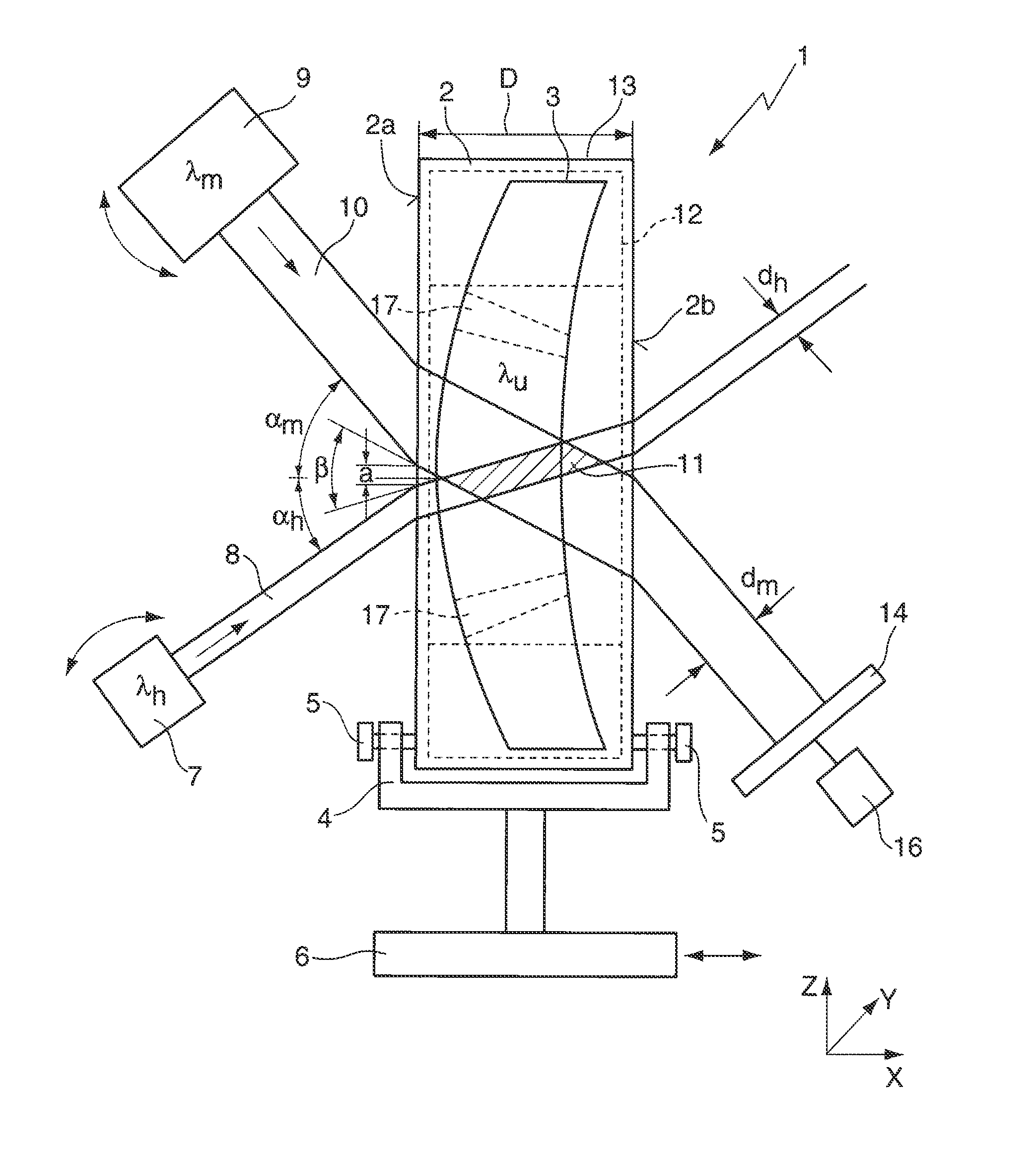
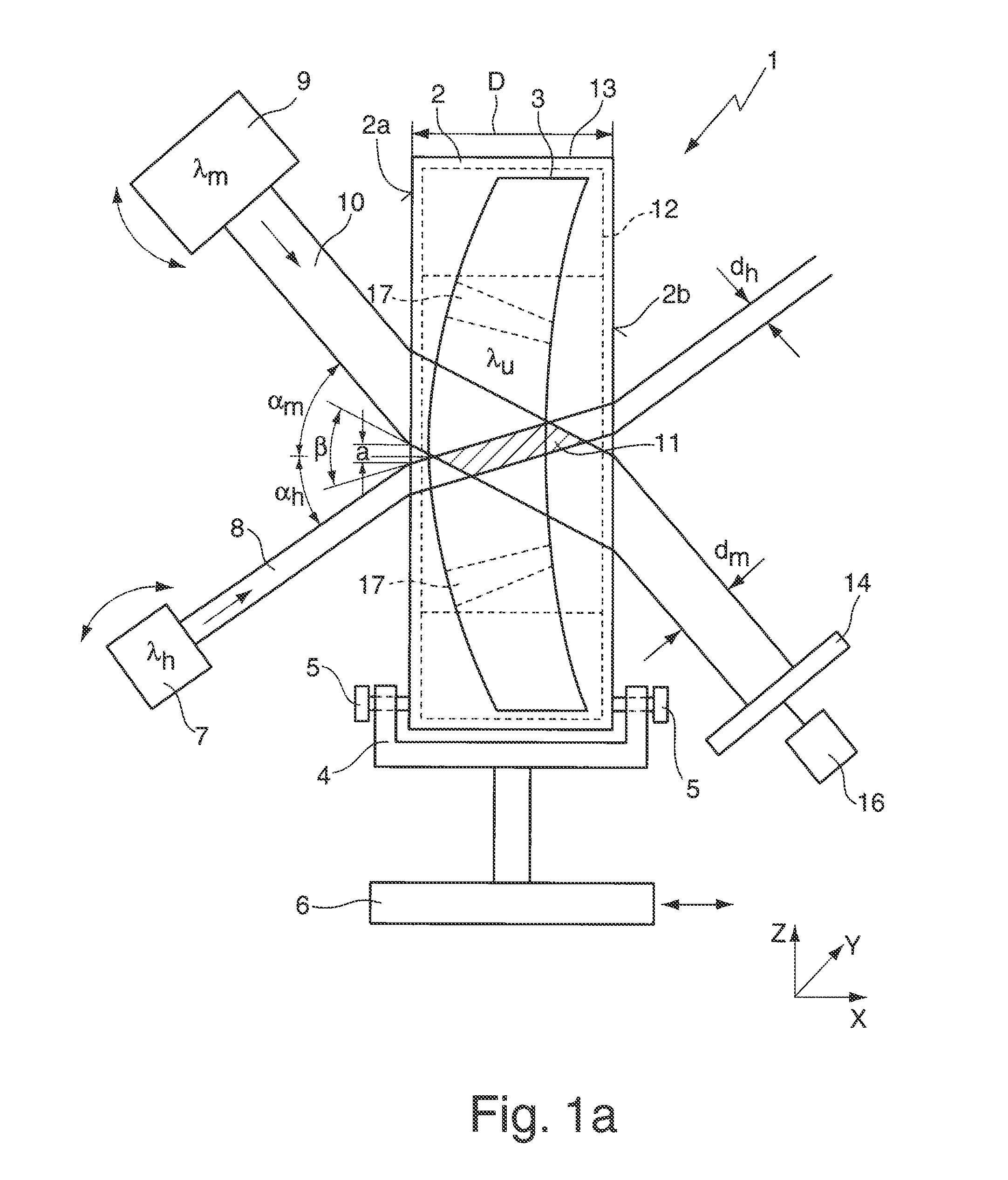
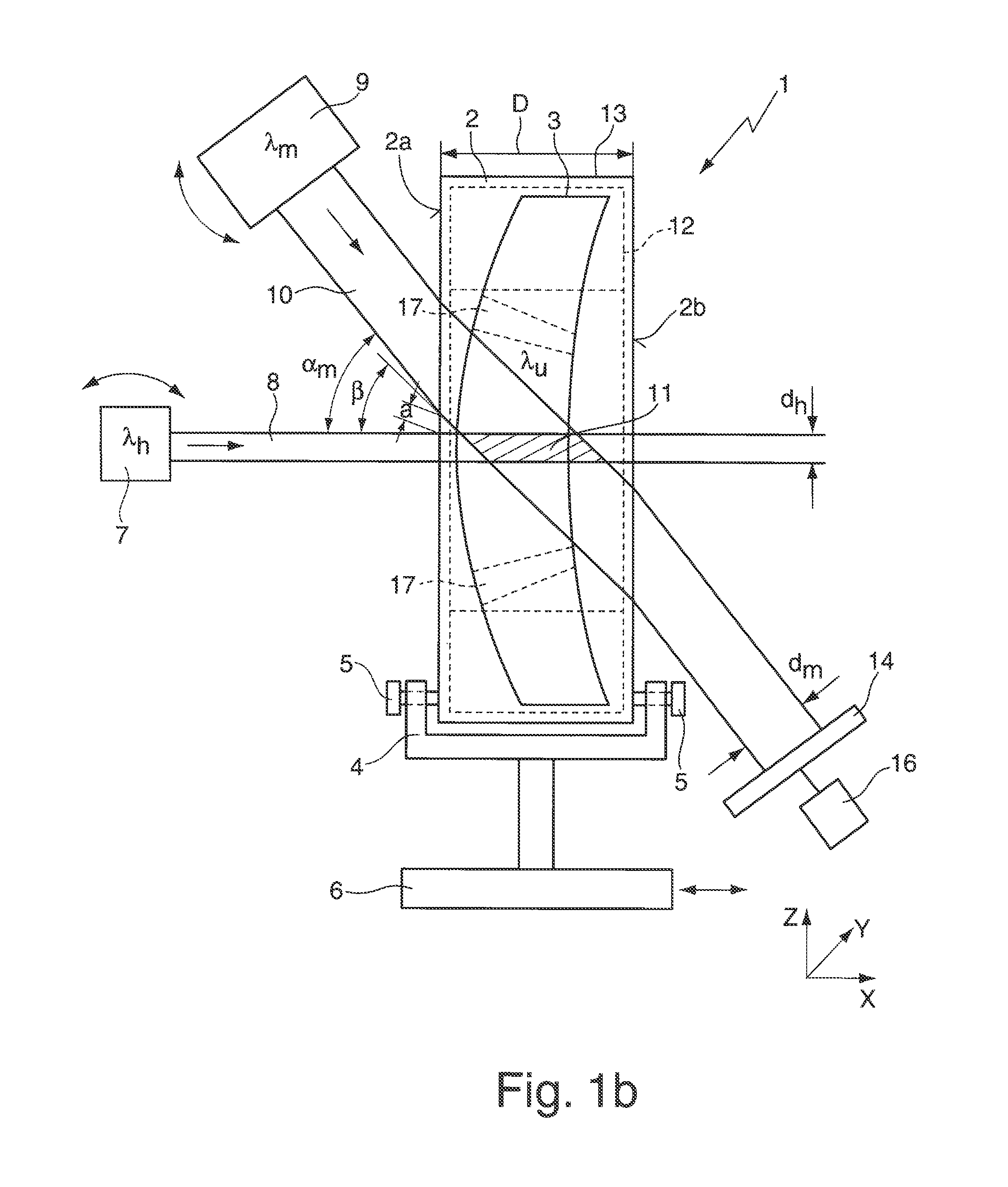
[0055]FIG. 1a schematically illustrates an apparatus 1 for determining the absorption of a blank 2 for producing an optical element 3. Said apparatus has a holding device 4 (sample holder) for the blank 2, on which the latter is mounted in an upright fashion and fixed with the aid of adjusting screws 5. The end faces 2a, 2b of the cylindrical blank 2 are provided with a visible polish, i.e. the end faces 2a, 2b have a residual roughness having a polishing quality in the range of the polishing class P1 or P2. The sample holder 4 is arranged on a displacing table 6, which, with the aid of linear drives, enables a displacement—indicated by a double-headed arrow—of the blank 2 in three axial directions X, Y, Z perpendicular to one another. It goes without saying that the apparatus 1 can, if appropriate, also be used for measuring a ground and polished optical element 3.

[0056]The apparatus 1 furthermore has a heating light source 7 for generating a (collimated) heating light ray 8 for he...


PUM


Abstract

A method for determining the absorption of a blank (2) for producing an optical element (3), including: radiating a heating light ray (8) through the blank (2) for the purpose of heating the blank (2), and determining the absorption in the blank (2) by measuring at least one property of a measurement light ray (10) influenced by the heating of the blank (2). In the method, either the heating light ray (8) and the measurement light ray (10) or the heating light ray and a further heating light ray are oriented to enter into the blank (2) through a first polished surface (2a) or a second polished surface (2b), situated opposite the first surface, and meet one another exclusively in the interior of the blank (2), preferably in a volume (12) used for the production of the optical element (3). An associated measuring apparatus (1), optical element (3), and optical arrangement are also disclosed.

Description

CROSS-REFERENCE TO RELATED APPLICATIONS[0001]The present application is a Continuation of International Application No. PCT / EP2012 / 061105, filed on Jun. 12, 2012 claims priority under 35 U.S.C. §119(a) to German Patent Application No. 10 2011 078 885.9, filed on Jul. 8, 2011, also claims the benefit under 35 U.S.C. 119(e)(1) of U.S. Provisional Application No. 61 / 505,718, filed on Jul. 8, 2011. The disclosures of these three applications are hereby incorporated into the present application by reference in their respective entireties.FIELD AND BACKGROUND OF THE INVENTION [0002]The invention relates to a method for determining the absorption of a blank for producing an optical element, comprising: radiating a heating light ray through the blank for the purpose of heating the blank, and determining the absorption in the blank by measuring at least one property of a measurement light ray influenced by the heating of the blank. The invention also relates to an apparatus for determining t...

Claims


Application Information

Patent Timeline
IPC IPC(8): G01N21/17G02B13/14
CPCG02B13/143G01N21/17G01N21/171G01M11/0285G01M11/0257G01N2021/1712
Inventor EVA, ERIC
Owner CARL ZEISS SMT GMBH
Learn More