
Rim, airless tire and hubcap designs configured to directionally convey air and methods for their use

Inactive Publication Date: 2014-07-10
GEBEAU GARY
View PDF10 Cites 23 Cited by
  • Summary
  • Abstract
  • Description
  • Claims
  • Application Information

AI Technical Summary

Benefits of technology

The patent is about a new device that redesigns the rims, hubcap, and tires of a vehicle to improve its traction and reduce its center of gravity as it moves faster. It also provides cooling airflow to brake components.

Problems solved by technology

This lift reduces traction between the vehicle and the road surface, which is highly undesirable and can create an extremely hazardous driving condition.
Specifically, rear spoilers create a downward force on the rear axle, improving traction between the rear wheels and the road and front spoilers located at the underside of the front of the car, disrupt airflow as it travels beneath the car, creating a partial vacuum, which can cause the vehicle body to be pulled toward the ground, increasing traction between all wheels and the road.
Although both types of spoilers provide some downward force on a vehicle, thus increasing traction, neither is an ideal solution.
Specifically, front spoilers (air dams) are often located close to the ground where they can easily be damaged by uneven road surfaces.
Additionally, the ability to retract these spoilers is minimal at best.
However, these spoilers are located on the back end of a vehicle, and depending on the type of vehicle, may not be visually appealing to the owner and can be an obstacle that reduces the driver's rear visibility.
Moreover, this location does not allow for the downward force to be evenly distributed over the entire length of the vehicle.
Friction between the brake pads and brake discs or drums creates a significant amount of heat.

Method used


Image

  • Rim, airless tire and hubcap designs configured to directionally convey air and methods for their use
  • Rim, airless tire and hubcap designs configured to directionally convey air and methods for their use
  • Rim, airless tire and hubcap designs configured to directionally convey air and methods for their use

Examples


Embodiment Construction

[0045]This description of the exemplary embodiments is intended to be read in connection with the accompanying drawings, which are to be considered part of the entire written description. In the description, relative terms such as “lower,”“upper,”“horizontal,”“vertical,”, “above,”“below,”“up,”“down,”“top” and “bottom” as well as derivative thereof (e.g., “horizontally,”“downwardly,”“upwardly,” etc.) should be construed to refer to the orientation as then described or as shown in the drawing under discussion. These relative terms are for convenience of description and do not require that the apparatus be constructed or operated in a particular orientation. Terms concerning attachments, coupling and the like, such as “connected” and “interconnected,” refer to a relationship wherein structures are secured or attached to one another either directly or indirectly through intervening structures, as well as both movable or rigid attachments or relationships, unless expressly described othe...


PUM

PropertyMeasurementUnit
Angleaaaaaaaaaa
Flow rateaaaaaaaaaa
Diameteraaaaaaaaaa

Abstract

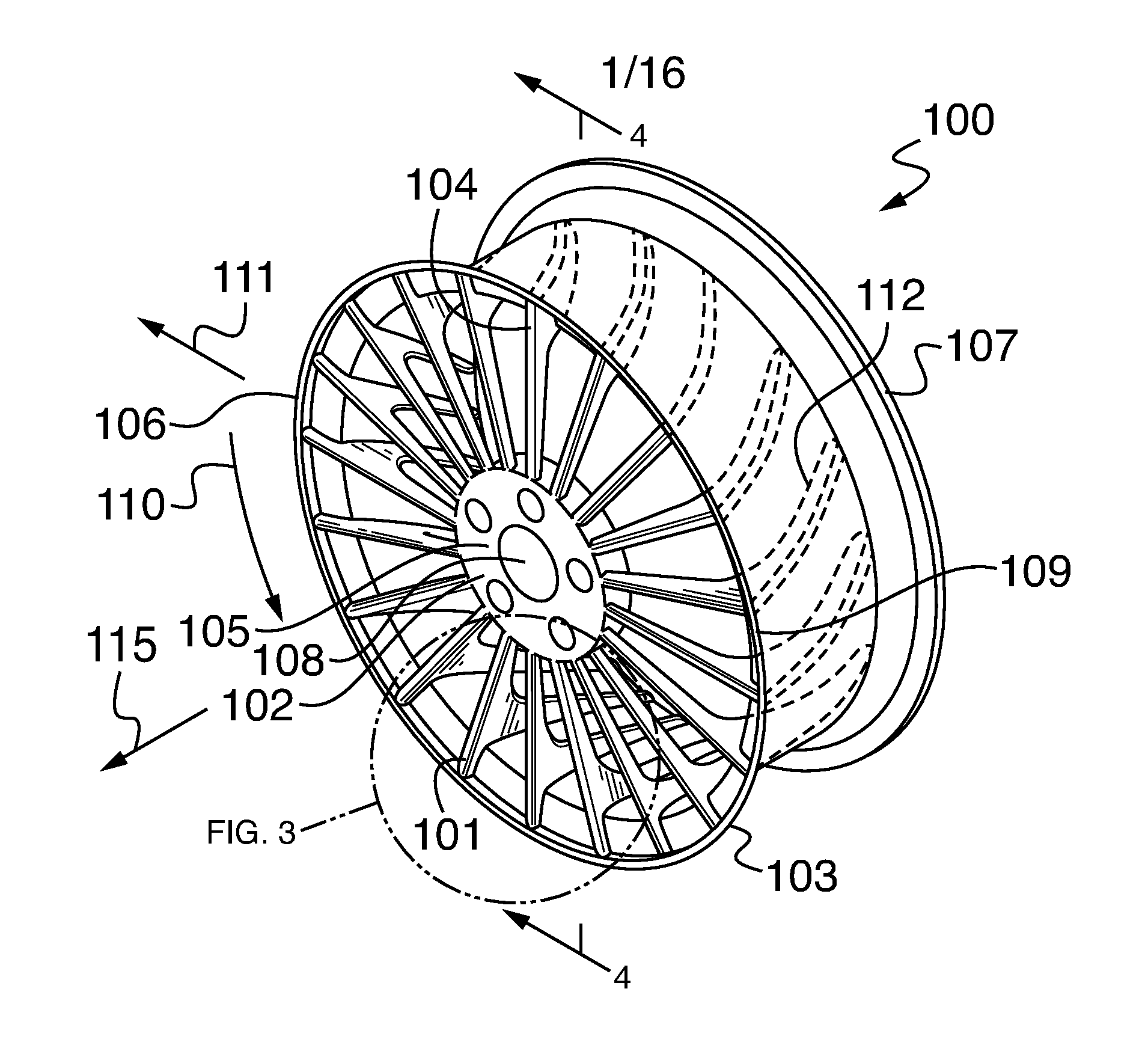
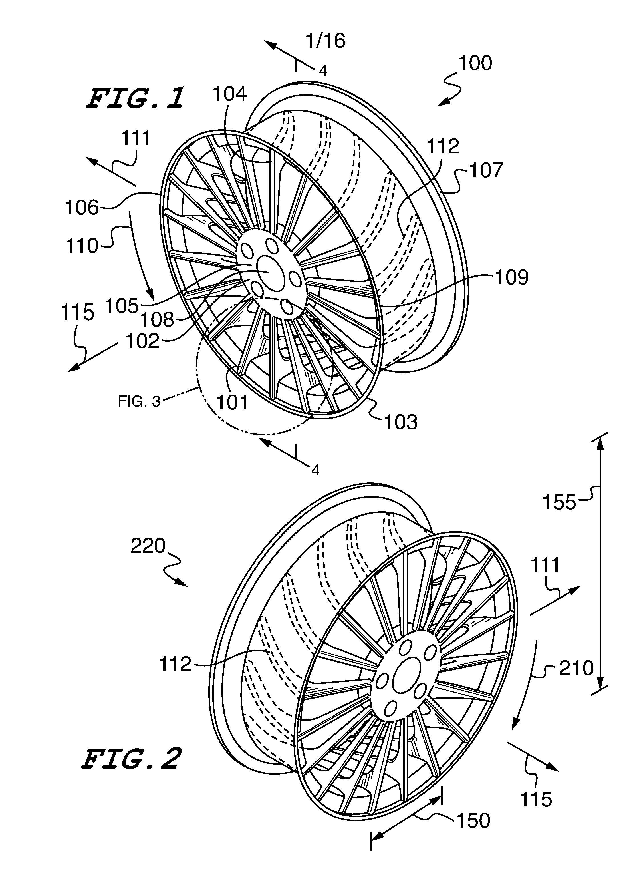
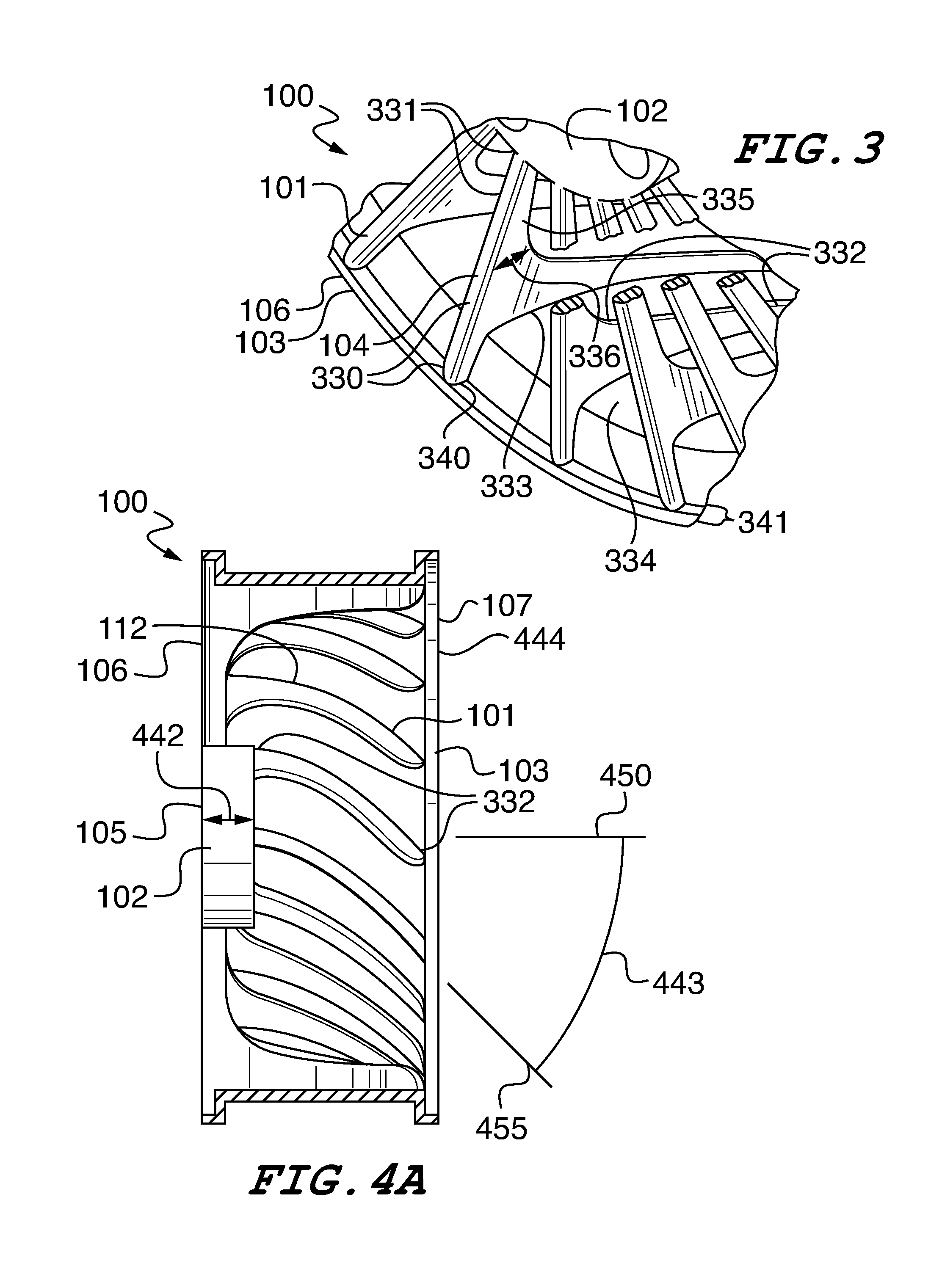
The present turbine fan rim, turbine fan airless tire and turbine fan hubcap designs are configured to remove air from under the underside of a moving vehicle when rotated in a particular direction, typically in a forward direction. This air movement can create a vacuum below the vehicle, which can create a down force on the vehicle increasing traction between the vehicle's tires and the road surface and lowering the vehicle's center of gravity. This downward force and partial vacuum can thus increase as the rotational velocity of the tires increases, providing greater traction at higher speeds. An additional benefit to these wheel, airless tire, and hubcap designs is the cooling effect that would be created by the flowing air on brake parts that are located near wheels of nearly all vehicles.

Description

FIELD OF THE INVENTION[0001]The present rim, airless tire an hubcap designs can comprise spokes, supports or similar structures configured to operate as turbine fan vanes, which can move air from under a vehicle as the vehicle moves forward. The movement of air from under the vehicle creates a partial vacuum under the vehicle, which generates a downward force which acts to pull the vehicle body towards the ground lowering the vehicle's center of gravity. This downward force presses each of the wheels against the ground resulting in increased traction and vehicle stability. The volume of air moved increases as speed increases due to fact that the wheels and turbine fan vanes rotate at higher RPMs (revolutions per minute) as speed increases. The result is the creation of a more powerful vacuum under the vehicle at higher speeds when greater traction and stability are required most. The present rim, airless tire and hubcap designs can also create increased airflow over the brakes, whic...

Claims


Application Information

Patent Timeline
IPC IPC(8): B60B7/00B60C7/00B60B31/00B60B15/00
CPCB60B15/00B60C7/00B60C7/143B60C2007/107B60C2007/146B60B3/007B60B2900/513B60B7/0086B60B7/02B60B7/18B60B19/10B60B2900/3312B60B3/10Y10T29/49492B60C7/146B60C7/107
Inventor GEBEAU, GARY
Owner GEBEAU GARY
Learn More