
Method for controlling power flow within a wind park system, controller, computer program and computer program products

a technology of wind power generation and control, applied in the direction of electric generator control, machine/engine, mechanical apparatus, etc., can solve the problems of high risk of instability between control systems of parallel-connected off-shore vsc converters, mechanical inertia, and difficulty in implementing conventional power control using frequency droop, so as to achieve reliable control of parallel-connected wind parks and fast load sharing

Active Publication Date: 2014-07-10
HITACHI ENERGY SWITZERLAND AG
View PDF5 Cites 20 Cited by
  • Summary
  • Abstract
  • Description
  • Claims
  • Application Information

AI Technical Summary

Benefits of technology

The invention aims to provide better control over wind parks that are connected parallel to each other. This helps to quickly share the load when there is a high demand, as well as during periods of low power generation.

Problems solved by technology

One challenge in this regards relates to the location of wind farms, typically being far from a main power grid.
However, there is a significant difference: mechanical inertia.
This entails the risk of instability between control systems of the parallel-connected off-shore VSC converters.
Conventional power control using frequency droop can be difficult to implement due to the lack of mechanical inertia.
In particular, it can be difficult to obtain stability of such system.

Method used


Image

  • Method for controlling power flow within a wind park system, controller, computer program and computer program products
  • Method for controlling power flow within a wind park system, controller, computer program and computer program products
  • Method for controlling power flow within a wind park system, controller, computer program and computer program products

Examples


Embodiment Construction

[0027]In the following description, for purposes of explanation and not limitation, specific details are set forth such as particular architectures, interfaces, techniques, etc. in order to provide a thorough understanding of the invention. However, it will be apparent to those skilled in the art that the invention may be practiced in other embodiments that depart from these specific details. In other instances, detailed descriptions of well-known devices, circuits, and methods are omitted so as not to obscure the description of the invention with unnecessary detail. Like numbers refer to like elements throughout the description.

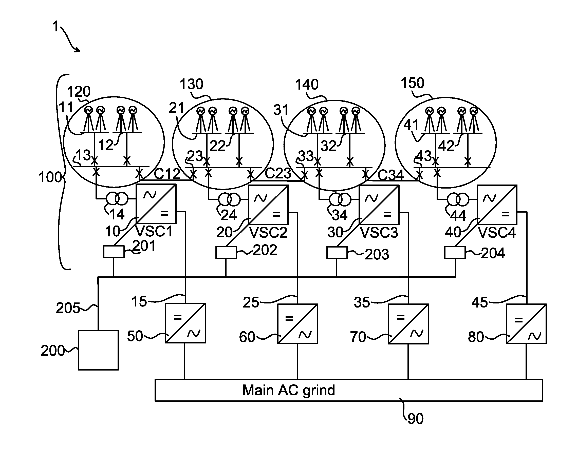
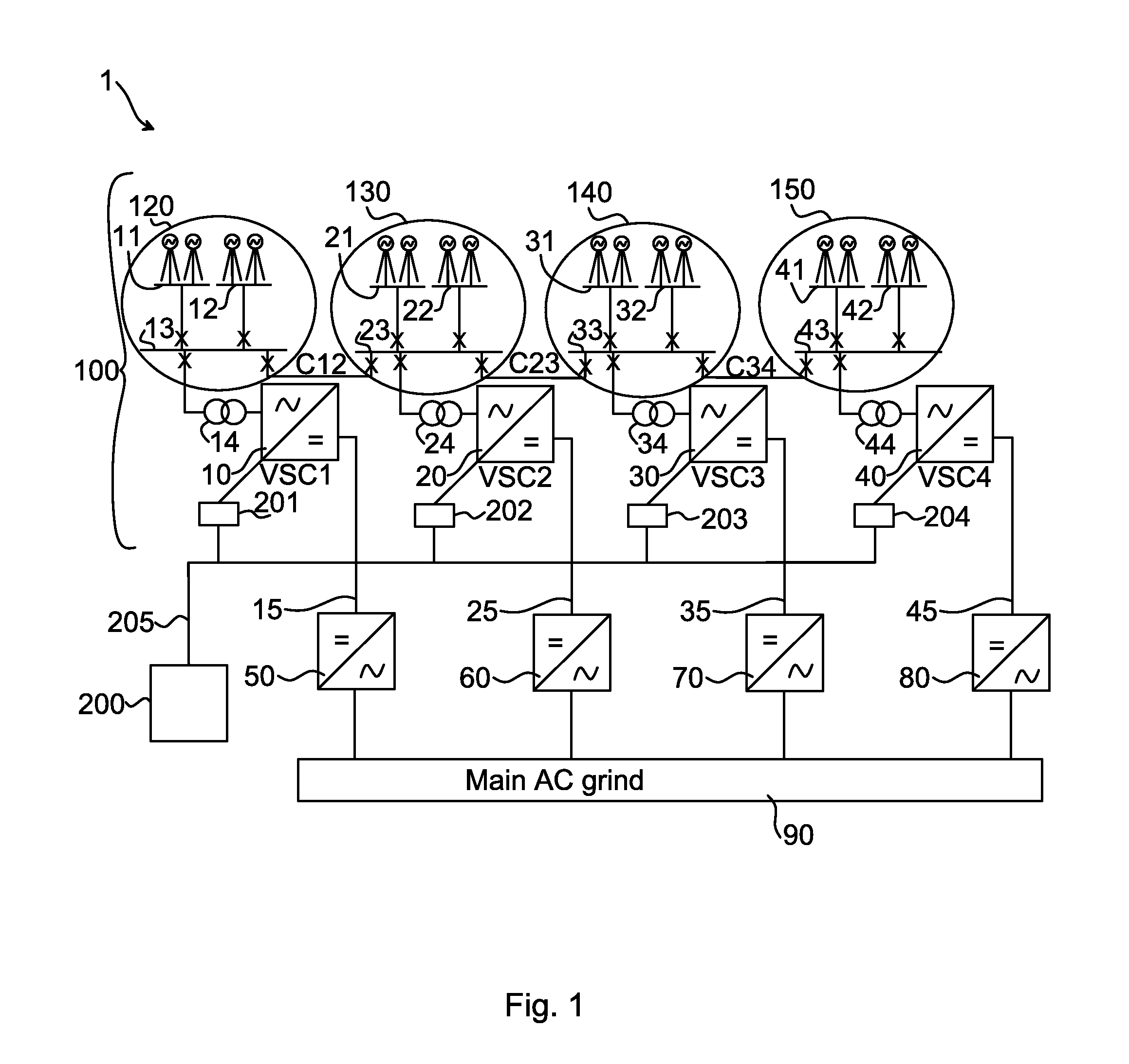
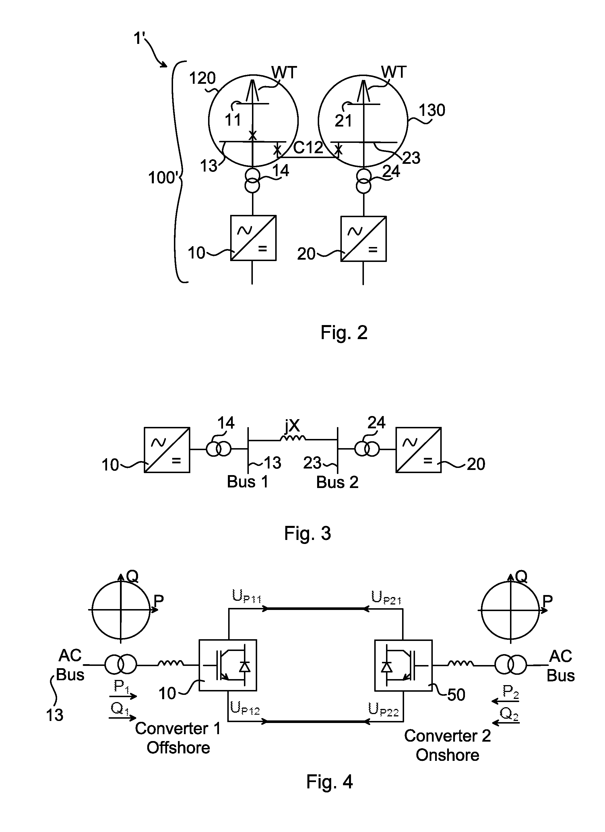
[0028]FIG. 1 illustrates schematically an environment in which embodiments of the invention may be implemented. The maximum power from a large off-shore wind park system 100 is larger than the capability of a single HVDC connection. Therefore, several HVDC links (transmission lines 15, 25, 35, 45) are needed, which may be connected in parallel as illustrated...


PUM


Abstract

The invention relates to a method for controlling power flow within a wind park system (100) for power transmission to a main power grid (90), the wind park system (100) comprising two or more parallel-connected island wind park grids. The method comprises the steps of: controlling a first voltage source converter (10) as a swing bus in frequency control, the frequency control comprising controlling frequency to a steady state reference operating point for operating points within a power dead band and by means of frequency droop control when exceeding an end point of the power dead band, and controlling at least a second voltage source converter (20), (30), (40) in power control, the power control comprising controlling power flow to a steady state reference operating point for operating points within a frequency dead band and by means of power droop control when exceeding an end point of the frequency dead band. The invention also relates to controllers, computer programs and computer program products.

Description

FIELD OF THE INVENTION[0001]The invention relates generally to the field of wind power generation and control thereof, and in particular control of parallel connected wind park grids.BACKGROUND OF THE INVENTION[0002]To use wind energy from wind power plants is an attractive although challenging alternative for power generation. One challenge in this regards relates to the location of wind farms, typically being far from a main power grid. The power from the wind parks has to be delivered to the main power grid in an efficient and reliable manner. High Voltage Direct Current (HVDC) transmission for interconnecting e.g. an off-shore wind park to the on-shore main power grid is considered a suitable alternative.[0003]Operation of parallel voltage source converter (VSC) HVDC links feeding the power from the off-shore wind park to the main land may seem very straight forward in that strategies used for operating parallel generators feeding the main power grid could be used. However, ther...

Claims


Application Information

Patent Timeline
Patent Type & Authority Applications(United States)
IPC IPC(8): F03D9/00H02J3/04H02J3/46H02J3/36
CPCF03D9/005H02J3/46H02J3/36H02J3/04Y02E60/60F03D7/0284F03D7/048F05B2270/337F03D9/257H02J3/388H02J2300/28H02J3/381Y02E10/72Y02E10/76
Inventor HOLMBERG, PERJIANG-HAFNER, YINGJUHLIN, LARS-ERIK
Owner HITACHI ENERGY SWITZERLAND AG
Learn More