System And Method For Controlling A Vehicle System

a vehicle system and control system technology, applied in vehicle position/course/altitude control, process and machine control, instruments, etc., can solve the problems of engine overheating and/or less power, engine overheating, engine components can overheat, etc., to achieve the effect of decreasing increasing the size of the vehicle system

Active Publication Date: 2014-06-26
GE GLOBAL SOURCING LLC
View PDF4 Cites 50 Cited by
  • Summary
  • Abstract
  • Description
  • Claims
  • Application Information

AI Technical Summary

Benefits of technology

This patent is about a system for distributing power to a vehicle system so that it can keep its speed high enough to pass through restricted airflow areas. The system takes into account factors like the size of the vehicle, the grade and curvature of the route, and other factors to determine the minimum amount of power needed to maintain speed. The power output is kept above the minimum amount to make sure the vehicle travels at least as fast as the speed threshold in the restricted airflow areas. The technical effect of this patent is to enable the vehicle system to pass through restricted airflow areas with high speed and efficiency.

Problems solved by technology

However, these vehicle systems also may travel through areas where there is insufficient oxygen supply and / or ventilation.
For example, during travel in a tunnel, there may an insufficient supply of oxygen available for combustion by the engines of the vehicle systems.
As a result of the decreased oxygen and / or intake of exhaust, the engines may overheat and / or produce less power.
Without sufficient airflow, components of the circuits can overheat over time.
For example, during travel in a tunnel, there may insufficient airflow to adequately cool transformers, inverters, and the like of the circuits onboard the vehicles.
As a result of the restricted airflow, the power output of the vehicles and / or time during which the vehicles may operate can be limited.
The decrease in power generated by the engines can cause the vehicle system to slow down and / or stop in the tunnel.
Additionally, the length of tunnels may be limiting due to the inability of the engines and / or circuits to operate for extended periods of time within the tunnels.

Method used


Image

  • System And Method For Controlling A Vehicle System
  • System And Method For Controlling A Vehicle System
  • System And Method For Controlling A Vehicle System

Examples


Embodiment Construction

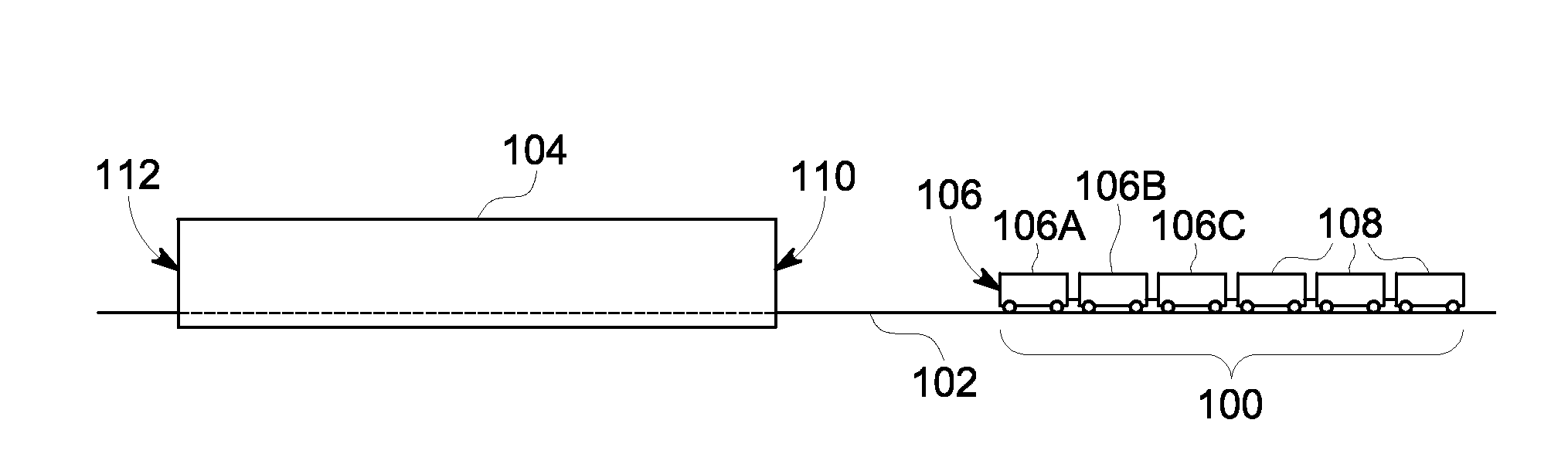
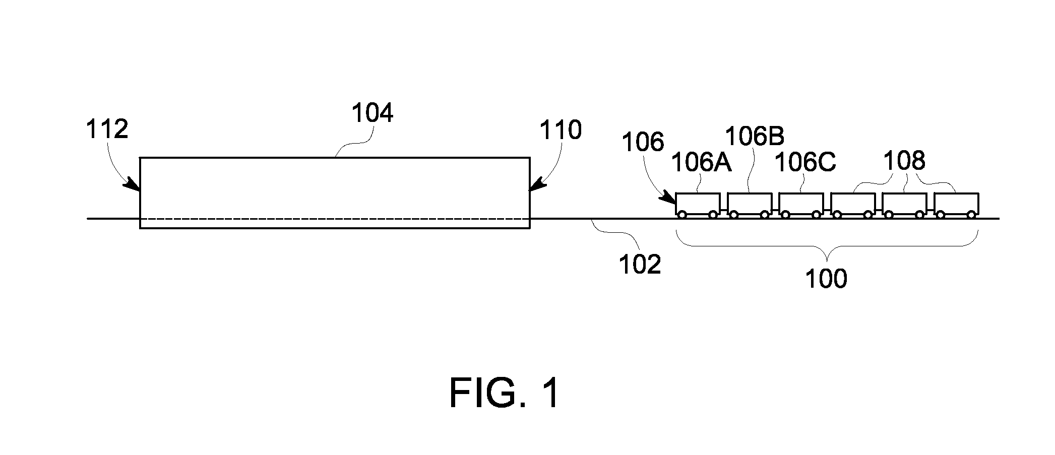
[0027]FIG. 1 illustrates a schematic diagram of one example of a vehicle system 100 traveling along a route 102 toward an airflow restricted area 104. FIGS. 4 through 6 illustrate additional diagrams of the vehicle system 100 entering, traveling within, and exiting from the airflow restricted area 104. The vehicle system 100 includes several vehicles 106, 108 connected with each other, such as by couplers. The vehicles 106 (e.g., vehicles 106A-C) represent propulsion-generating vehicles, such as vehicles capable of generating propulsive force to propel the vehicle system 100 along the route 102. Although the vehicles 106A-C are shown as being directly coupled with each other, two or more of the vehicles 106A-C may be separated from one another by one or more of the vehicles 108. Examples of propulsion-generating vehicles 106 include locomotives, other off-highway vehicles (e.g., vehicles that are not designed for or permitted to travel on public roadways), automobiles (e.g., vehicle...


PUM


Abstract

A method for controlling a vehicle system includes determining when the vehicle system approaches an airflow restricted area and distributing a total power output of the vehicle system among first and second vehicles of the vehicle system. The total power output is distributed by directing the first vehicle to decrease power output relative to a power output generated by the second vehicle and / or by directing the second vehicle to increase power output relative to the power output generated by the first vehicle. The method includes monitoring the power output of the second vehicle during travel of the vehicle system in the airflow restricted area to determine when the second vehicle derates and redistributing the total power output of the vehicle system among the at vehicles as the vehicle system travels in the airflow restricted area and responsive to the second vehicle derating.

Description

TECHNICAL FIELD[0001]Embodiments of the subject matter described herein relate to controlling operations of a vehicle system.BACKGROUND[0002]Some known vehicle systems include multiple vehicles connected together so that the vehicles can travel together. Such vehicle systems can be referred to as consists. For example, rail vehicle consists may include two or more locomotives and one or more railcars connected together. The vehicle systems may have engines that consume fuel and air (e.g., oxygen) to generate propulsive force and travel in open areas having sufficient oxygen supply and ventilation to allow engines of the vehicle systems to provide full power output (e.g., for the horsepower ratings of the engines).[0003]However, these vehicle systems also may travel through areas where there is insufficient oxygen supply and / or ventilation. For example, during travel in a tunnel, there may an insufficient supply of oxygen available for combustion by the engines of the vehicle systems...

Claims


Application Information

Patent Timeline
IPC IPC(8): B60W20/00B60W10/08B60W10/06
CPCB60W20/00Y10S903/93B60W10/08B60W10/06B60W30/18009B60W2510/0628B60W2710/0677B60Y2200/31Y02T10/62
Inventor DAUM, WOLFGANG
Owner GE GLOBAL SOURCING LLC
Why Eureka
Try Eureka