
Measured value transmitting device

a technology of transmitting device and measured value, which is applied in the direction of data conversion, transmission system, and redundant data error correction, can solve problems such as erroneous transmission of measured value, and achieve the effect of increasing the security of measured value transmission

Active Publication Date: 2014-06-19
BALLUFF
View PDF5 Cites 5 Cited by
  • Summary
  • Abstract
  • Description
  • Claims
  • Application Information

AI Technical Summary

Benefits of technology

The measured value data transmitting device described in this patent increases security by identifying errors in the clock signal. This is helpful in preventing incorrect transmission of measured values due to interference pulses or errors in clock cycles. The device also includes a checking of the duty cycle for an additional measure of security. This combination of measures ensures that data is transmitted accurately and safely, even in situations where the master and slave are separated far from each other. The use of the established SSI method minimizes the necessary changes to the hardware.

Problems solved by technology

A wrong number of clock cycles within a clock burst would lead to an erroneous transmission of measured values.

Method used


Image

  • Measured value transmitting device
  • Measured value transmitting device
  • Measured value transmitting device

Examples


first embodiment

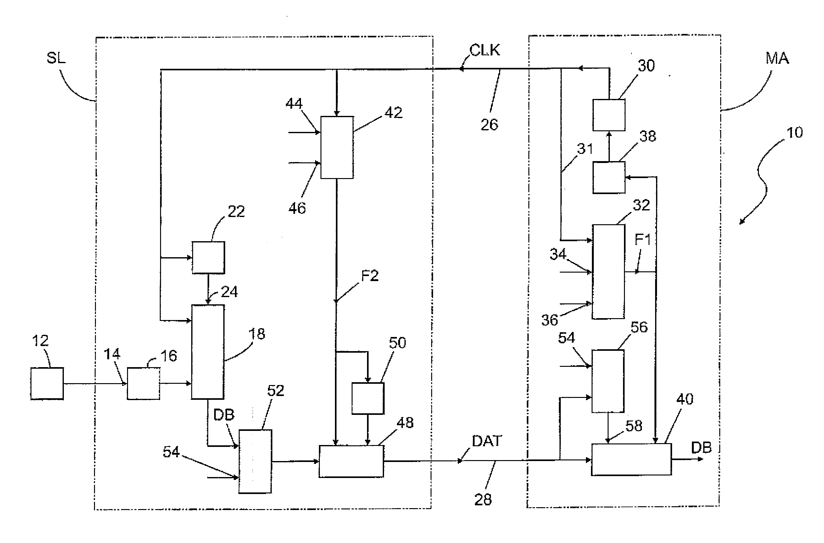
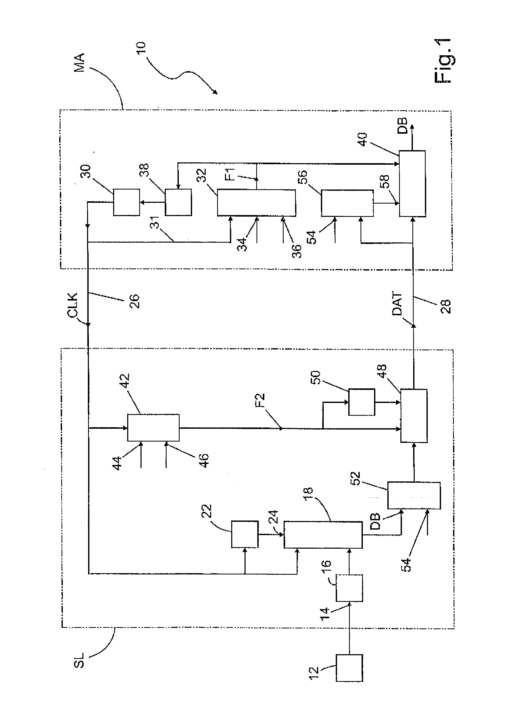
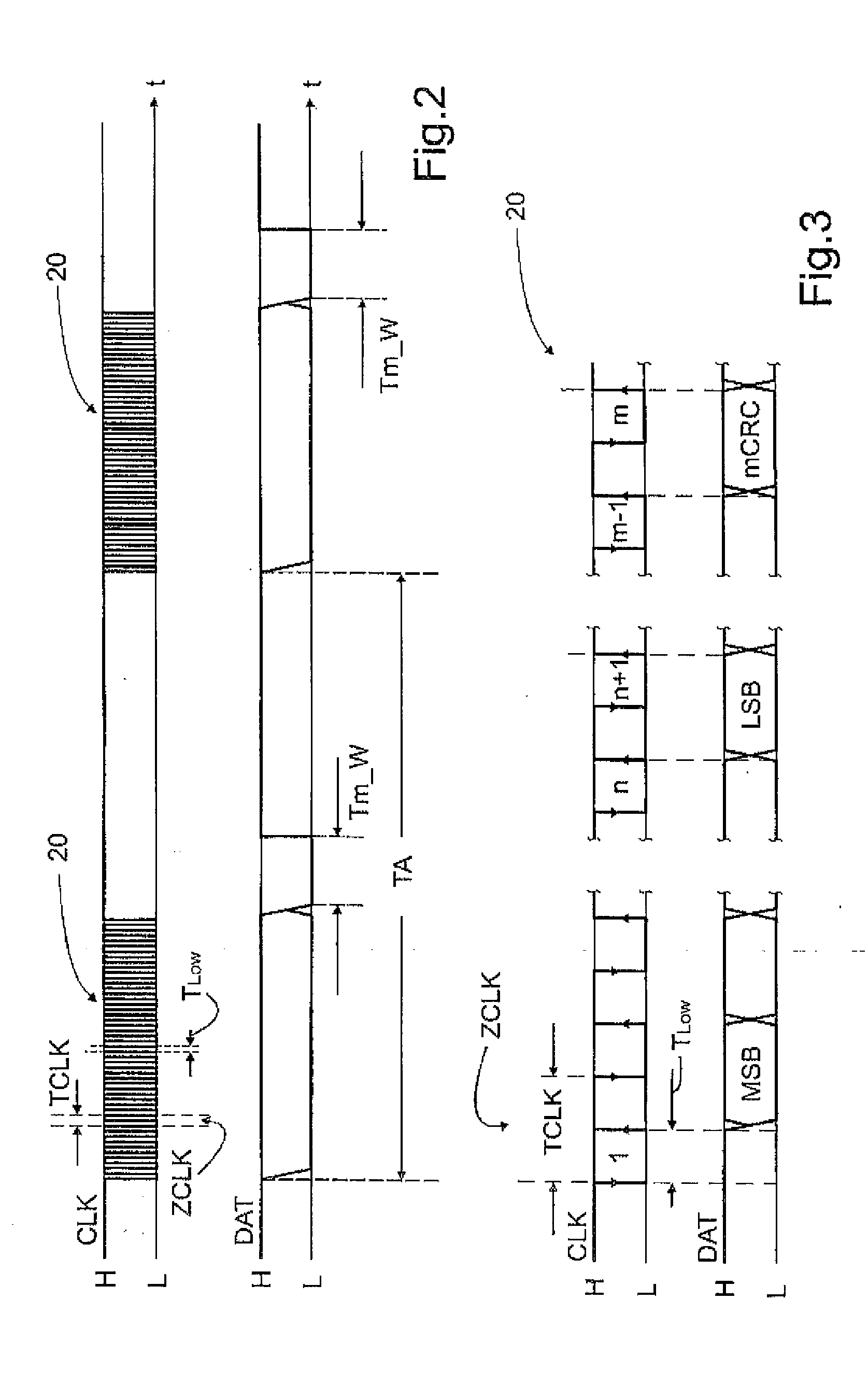
[0040]It is provided according to the invention that the clock signal CLK generated by a clock generator 30 in the master MA is read back and evaluated by the master MA itself. The readback means that the master MA reads in the clock signal CLK again, which was generated by its clock generator 30 and provided on the clock line 26, via a return feed line 31 from the clock line 26 and evaluates said signal itself. The clock signal CLK is supplied via a return feed line 31 to a first comparator 32 arranged in the master MA. The first comparator 32 evaluates the duty cycle TLow / TCLK by comparison with an upper and / or lower threshold value 34, 36.

[0041]The at least one threshold value 34, 36 is determined for example in such a way that any exceeding of the duty cycle TLow / TCLK of 10% for example and a respective falling below said value lead to a first error signal F1, which is provided for example to a clock repetition arrangement 38 and a data signal release 40.

[0042]FIG. 4a assumes a ...

second embodiment

[0045]It is provided according to the invention that a second comparator 42 is provided in the slave SL, which comparator also compares the duty cycle TLow / TCLK of the clock cycles ZCLK of the clock burst 20 of the clock signal CLK with an upper and / or lower threshold value 44, 46. The at least one threshold value 44, 46 can be identical to the threshold value 34, 36 provided in the master MA. The at least one threshold value 44, 46 in the slave SL can also deviate from the at least one threshold value 34, 36 of the master MA. The at least one threshold value 34, 36 provided in the master MA can be designated as master-related threshold value 34, 36 and the at least one threshold value 44, 46 provided in the slave SL can be designated as slave-related threshold value 44, 46.

[0046]The second comparator issues a second error signal F2 if the duty cycle TLow / TCLK exceeds or falls below a threshold value 44, 46. The second error signal F2 is made available for example to a data signal c...


PUM


Abstract

The invention relates to measured value transmitting devices for serially transmitting data in accordance with the SSI method, Synchronous Serial Interface. At least one slave is provided which provides the data bits of a measured value detected by at least one sensor for the purpose of a serial bit-by-bit transmission to a master. The master requests a measured value from the slave by means of a clock burst that has multiple clock cycles, the number of which matches the number of the data bits to be transmitted. A first measured value transmitting device according to the invention is characterized in that the clock cycles of the clock burst have a specified duty cycle which corresponds to the ratio of the pulse duration to the period duration of one clock cycle, and the master contains a comparator. The master reads the clock bursts outputted on the at least one clock line and checks the duty cycle in the comparator to determine whether an upper threshold and / or a lower threshold has been exceeded. A second measured value transmitting device according to the invention is characterized in that a corresponding check of the duty cycle is carried out in the slave.

Description

[0001]The invention relates to a measured value transmitting device for serial data transmission between a slave and a master in accordance with the SSI method (Synchronous Serial Interface), in which a measured value detected by a sensor is conditioned by a slave associated with the sensor and is converted into a serial data stream and is transmitted to a master which processes the detected measured values.[0002]Such a measured value transmitting device, which is known as a result of its operating method as a “Synchronous Serial Interface (SSI)”, has been described in the published application EP 171 579 A1. The measured value transmitting device contains a master and at least one slave. The slaves are associated with the sensors, wherein several sensors may optionally be associated with a slave. The measured values detected by a sensor are provided by the sensor already in digital form as data bits. The data bits are continuously loaded in the slave into a shifting register within...

Claims


Application Information

Patent Timeline
IPC IPC(8): G06F11/10H04L1/00H03K3/3562
CPCG06F11/1004H04L1/0045H03K3/3562H04L7/0008H04L25/45H04L1/0061G08C19/28G06F5/06
Inventor HAHN, UWE
Owner BALLUFF
Learn More