
Image forming apparatus controlling feeding of long-edge and short edge printing paper and method for controlling the same

a technology of image forming apparatus and feeding method, which is applied in the direction of electrographic process apparatus, typewriters, instruments, etc., can solve the problems of large differences in printing performance and achieve the effect of improving printing performan

Inactive Publication Date: 2014-06-19
S PRINTING SOLUTION CO LTD
View PDF1 Cites 7 Cited by
  • Summary
  • Abstract
  • Description
  • Claims
  • Application Information

AI Technical Summary

Benefits of technology

This patent is about improving printing performance by providing an image forming apparatus and a method for controlling it. The goal is to overcome problems and disadvantages of conventional systems.

Problems solved by technology

However, in a situation such as a Publish On Demand (POD) system, the printing work may be several thousands of papers.
However, in performing of a large amount of printing work through a large-scale printing system such as a POD system or a printing device, the difference greatly impacts printing performance.

Method used


Image

  • Image forming apparatus controlling feeding of long-edge and short edge printing paper and method for controlling the same
  • Image forming apparatus controlling feeding of long-edge and short edge printing paper and method for controlling the same
  • Image forming apparatus controlling feeding of long-edge and short edge printing paper and method for controlling the same

Examples


Embodiment Construction

[0042]Exemplary embodiments of the present disclosure are described in detail with reference to the accompanying drawings

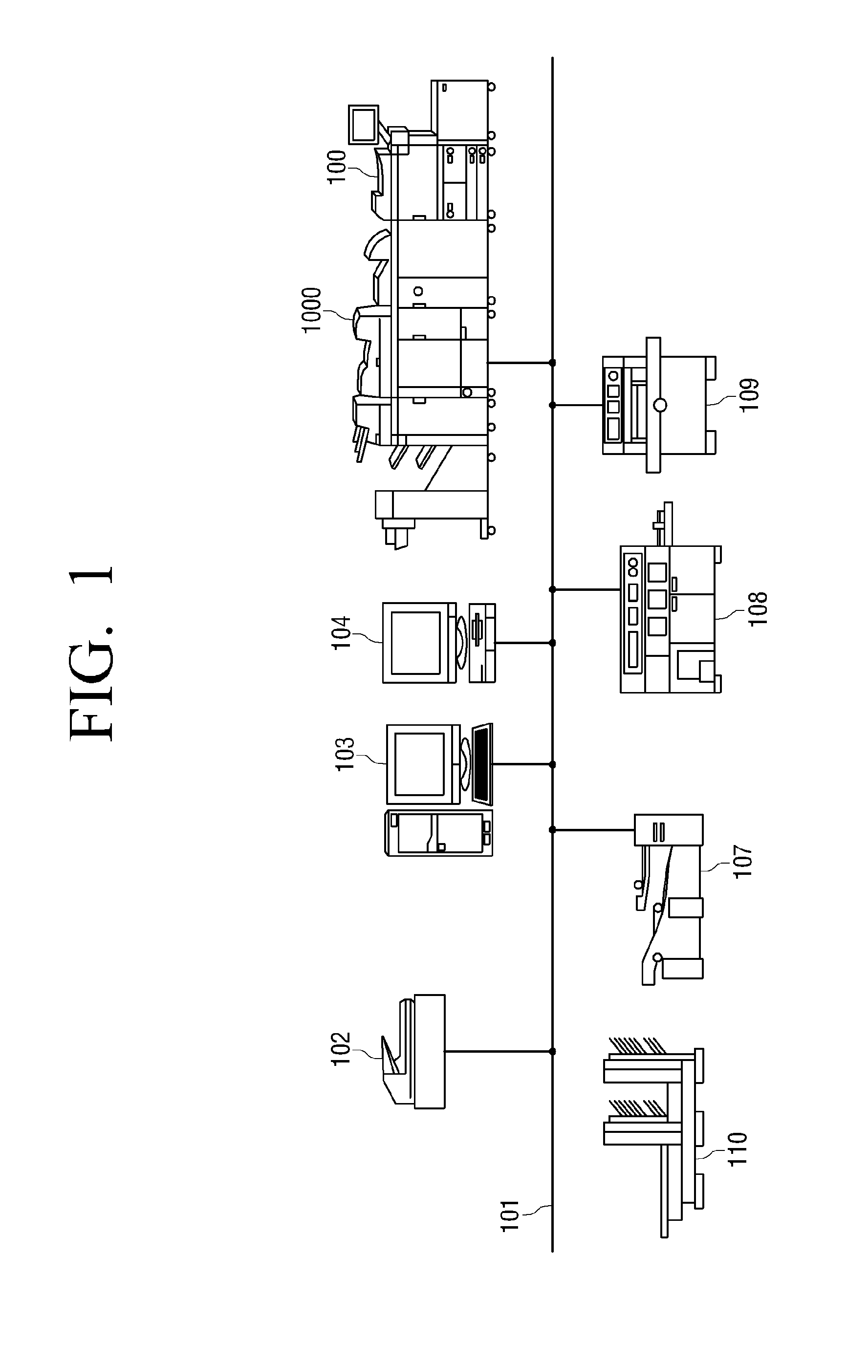
[0043]FIG. 1 illustrates a POD system according to an exemplary embodiment of the present disclosure.

[0044]An exemplary POD (Publish On Demand) system includes a printing system 1000, a scanner 102, a server computer (PC) 103, and a client computer 104, all of which may be connected through a network 101.

[0045]The POD system may include a finisher 107 that is a post-processing device capable of folding papers, a cover bookbinder 108, a cutter 109, and an intermediate bookbinder 110.

[0046]The server PC 103 manages data transmission / reception with various kinds of devices connected to the network 101. The client PC 104 uses the network 101, and transmits image data to a printing device 100 of the printing system 1000 or the server PC 103.

[0047]The finisher 107 performs folding and bookbinding process of the papers printed by the printing device 100.

[0048]The cover b...


PUM


Abstract

An image forming apparatus and method are provided. The apparatus includes a control unit controlling a feeder unit to feed a printing paper in a long-edge feed type or a short-edge feed type in accordance with a print mode set for print data. The control unit controls the feeder unit to feed the printing paper in the long-edge feed type upon a high resolution print mode being set and in the short-edge feed type upon a low resolution print mode being set.

Description

CROSS-REFERENCE TO RELATED APPLICATIONS[0001]This application is related to, and is a Divisional Application of pending U.S. application Ser. No. 13 / 200,367 filed on Sep. 23, 2011, and claims the benefit of priority to Korean Patent Application No. 10-2010-0104726, filed on Oct. 26, 2010, in the Korean Intellectual Property Office, the disclosures of which are incorporated herein by reference.BACKGROUND[0002]1. Field[0003]The embodiments disclosed herein are related to an image forming apparatus and a method for controlling the same, and more particularly, to an image forming apparatus of a multi-feed type and a method for controlling the same.[0004]2. Description of the Related Art[0005]Conventionally an image forming apparatus performs printing in a long-edge or short-edge feed mode.[0006]For example, in performing printing in a long-edge feed mode, an A4-sized portrait paper may be fed, and a printing time of one second required in printing. In performing printing in a short-edge...

Claims


Application Information

Patent Timeline
Patent Type & Authority Applications(United States)
IPC IPC(8): G03G15/00
CPCB41J3/60B41J11/485B41J13/0018G03G15/50
Inventor PARK, JEONG-YEONAHN, BYUNG-SUN
Owner S PRINTING SOLUTION CO LTD
Learn More