Method and a system for processing an image comprising dendritic spines

a technology of dendrite spines and images, applied in the field of image segmentation and processing, can solve the problems of inability to accurately detect the contours of dendrite spines, inability to accurately detect dendrite spines, and inability to provide a detailed description of how to precisely detect the spine contours

Inactive Publication Date: 2014-06-19
INST BIOLOGII DOSWIADCZALNEJ IM M NENCKIEGO PAN
View PDF2 Cites 14 Cited by
  • Summary
  • Abstract
  • Description
  • Claims
  • Application Information

AI Technical Summary

Benefits of technology

The invention is a computer-implemented method for processing images that include dendritic spines. The method involves detecting the tip point and base point of the dendritic spine, analyzing the brightness of consecutive image portions perpendicular to the axis of the tip point and base point, and selecting the brightest points as the contour points. The method can also approximate the contour points to a curve and determine various morphological parameters of the dendritic spine. The technical effect of the invention is to provide a reliable and automated method for analyzing dendritic spines in images, which can be useful in various fields such as neuroscience and biotechnology.

Problems solved by technology

However, no detailed description is provided how to precisely detect the contours of the spine.
There methods known so far are not accurate and cannot properly detect dendritic spines of unusual shapes, such as bent spines, nor are not immune to image artifacts, such as halo around the dendrite The method is especially suitable to images containing high amount of noise.

Method used


Image

  • Method and a system for processing an image comprising dendritic spines
  • Method and a system for processing an image comprising dendritic spines
  • Method and a system for processing an image comprising dendritic spines

Examples


Embodiment Construction

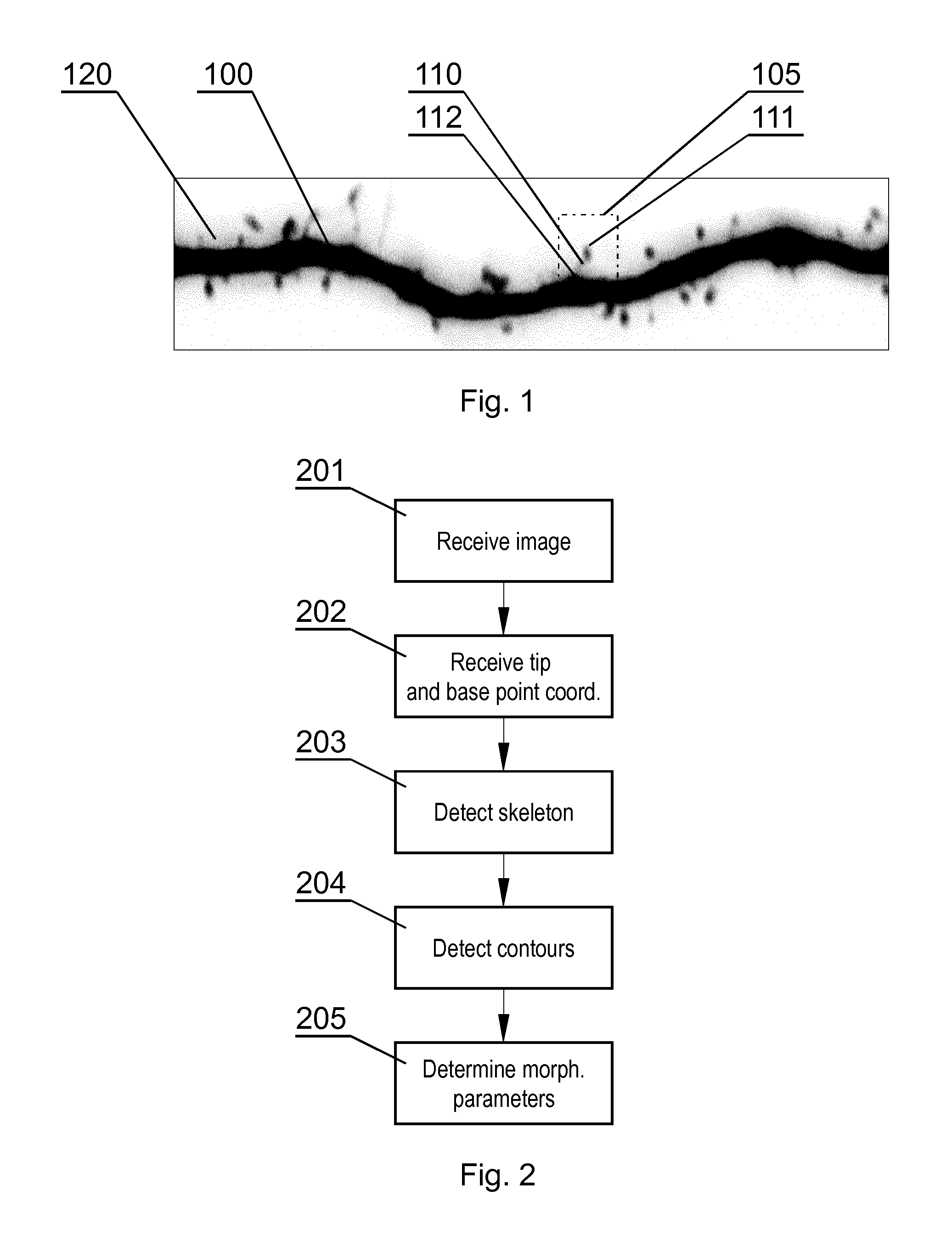
[0026]FIG. 1 shows an exemplary image comprising a dendrite 100 with dendritic spines 110, shown as an inverse image to improve the visibility. The image has been acquired by a fluorescence confocal microscope, with resulting pixel size 70 nm. The presented embodiment relates to a 2-dimensional image, but it can be used with 3-dimensional images in an equivalent manner as well.

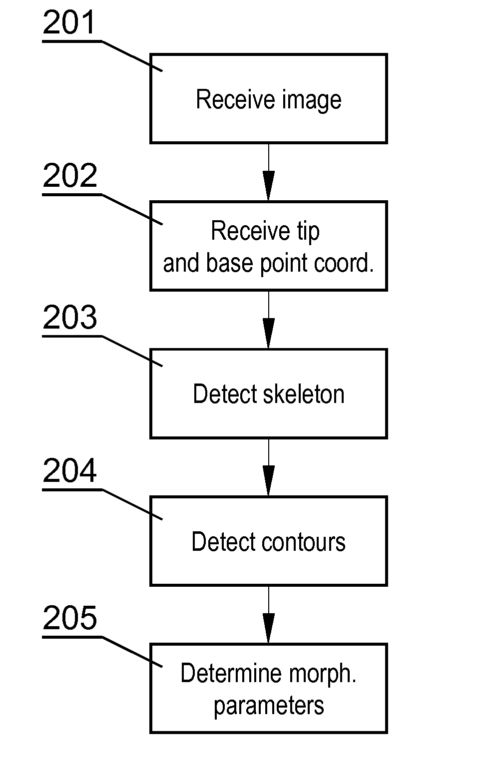
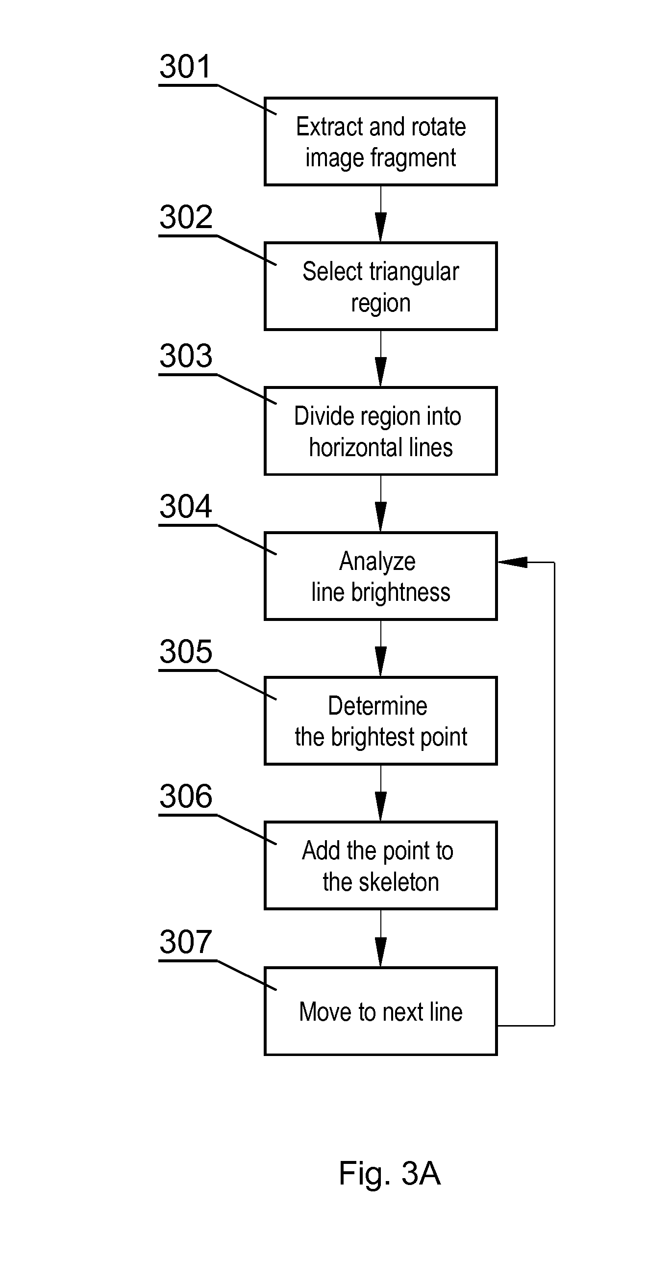
[0027]FIG. 2 shows the steps of the method according to the invention. The method starts in step 201 by receiving the image to be processed, such as the confocal microscope image shown in FIG. 1. Next, in step 202, coordinates of two points are received, namely the coordinates of the tip point 111 and the base point 112 of a dendritic spine which is to be segmented from the image, as shown in FIG. 1. The coordinates of the tip and base points may be defined by another algorithm or may be defined manually by the user. Next, in step 203, the skeleton of the dendritic spine is detected, as shown in FIG. 3. Then i...


PUM


Abstract

A computer-implemented method for processing an image comprising dendritic spines, the method comprising the steps of obtaining the image comprising at least one dendritic spine (110), obtaining the coordinates of the tip point (311) and the base point (312), detecting the skeleton (317) of the dendritic spine (110) by analyzing the brightness of consecutive image portions (316) arranged perpendicularly to an axis extending through the tip point (311) and the base point (312) and for each image portion (316) selecting the brightest point distanced not more than a predefined threshold (s) from the brightest point (314) of the previous image portion (316), detecting the contour (319) of the dendritic spine (310) by analyzing the brightness of consecutive image portions (318) arranged perpendicularly to the skeleton (317) and selecting the contour points (320) as points at which the plot brightness of the image portion transits the point having the brightness lower than the brightness (B) of the skeleton point multiplied by a brightness factor (η) at a furthest distance from the skeleton (317).

Description

TECHNICAL FIELD[0001]The present invention relates to image analysis and processing related to segmenting an image comprising dendritic spines.BACKGROUND ART[0002]A dendritic spine is a membrane protrusion from a neuron's dendrite that form postsynaptic component of synapses in the brain and typically receives input from a presynaptic part located on axon. Most spines have a bulbous head and a thin neck that connects the head to the shaft of the dendrite. The dendrites of a single neuron can contain hundreds to thousands of dendritic spines. Dendritic spines have a length of about 0.2 to 2 micrometers. The spine shape and volume is thought to be correlated with the strength and maturity of each spine-synapse. It was shown that morphology of the spine can be involved in synaptic plasticity as well as in learning and memory. Thus detailed and quantitative analysis of dendritic spine morphology is appealing issue of contemporary neuroscience. Knowledge about spine morphology is importa...

Claims


Application Information

Patent Timeline
Patent Type & Authority Applications(United States)
IPC IPC(8): A61B5/107A61B5/00G06T7/00
CPCG06T7/10G06V20/69A61B5/0068A61B5/0071A61B5/1079A61B5/4566G06T7/0012
Inventor RUSZCZYCKI, BLAZEJWLODARCZYK, JAKUBKACZMAREK, LESZEK
Owner INST BIOLOGII DOSWIADCZALNEJ IM M NENCKIEGO PAN
Why Eureka
Try Eureka