
Power supply apparatus with low standby power consumption

a power supply apparatus and standby mode technology, applied in the field of power supply apparatuses, can solve the problems of low standby power consumption waste of related art power supply apparatuses in standby mode, etc., and achieve the effect of low standby power consumption

Active Publication Date: 2014-06-19
CHICONY POWER TECH CO LTD
View PDF4 Cites 31 Cited by
  • Summary
  • Abstract
  • Description
  • Claims
  • Application Information

AI Technical Summary

Benefits of technology

The present invention aims to provide a power supply apparatus with low standby power consumption. This means that the apparatus should consume minimal power when it is not being actively used. This is important to reduce the energy waste and to improve the efficiency of the apparatus.

Problems solved by technology

However, the disadvantage of the related art power supply apparatus is that the standby power consumption of the related art power supply apparatus is not low enough.
The related art power supply apparatus still wastes too much energy in the standby mode.

Method used


Image

  • Power supply apparatus with low standby power consumption
  • Power supply apparatus with low standby power consumption
  • Power supply apparatus with low standby power consumption

Examples


Embodiment Construction

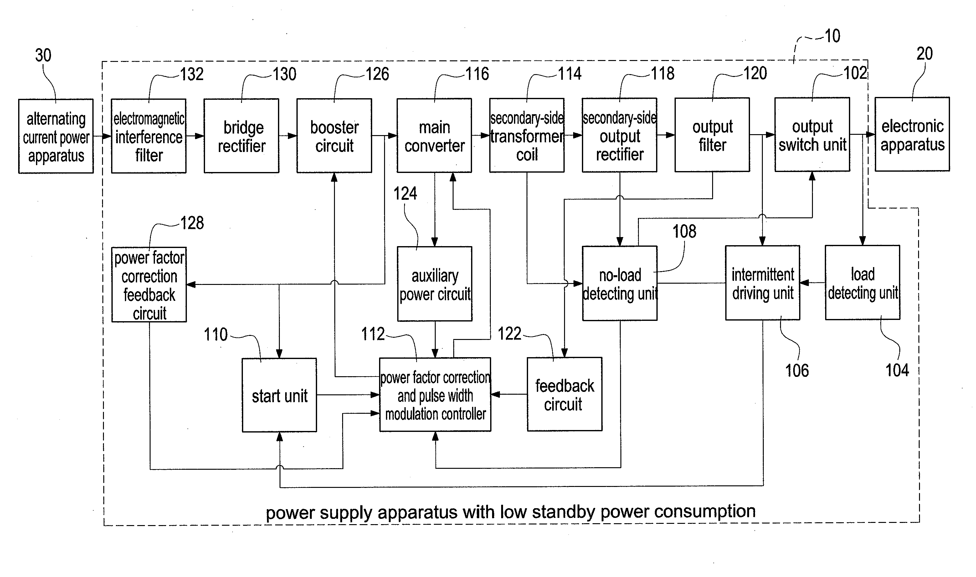
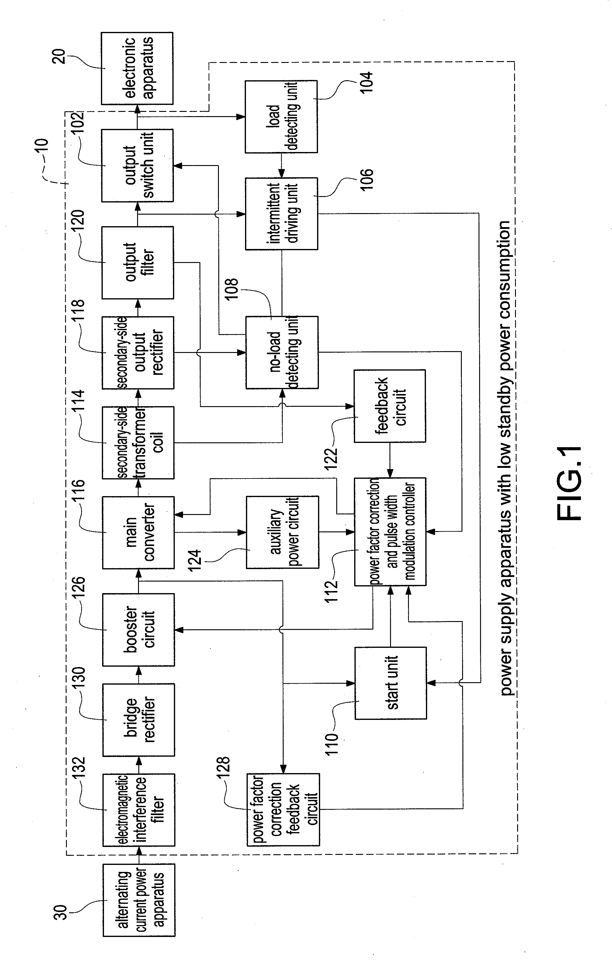
[0015]FIG. 1 shows a block diagram of the power supply apparatus with low standby power consumption of the present invention. A power supply apparatus 10 is applied to an electronic apparatus 20 and an alternating current power apparatus 30.

[0016]The power supply apparatus 10 includes an output switch unit 102, a load detecting unit 104, an intermittent driving unit 106, a no-load detecting unit 108, a start unit 110, a power factor correction and pulse width modulation controller 112, a secondary-side transformer coil 114, a main converter 116, a secondary-side output rectifier 118, an output filter 120, a feedback circuit 122, an auxiliary power circuit 124, a booster circuit 126, a power factor correction feedback circuit 128, a bridge rectifier 130, and an electromagnetic interference filter 132.

[0017]The power factor correction and pulse width modulation controller 112 is electrically connected to the no-load detecting unit 108, the start unit 110, the main converter 116, the f...


PUM


Abstract

An electronic apparatus is removed from a power supply apparatus and that can be certified by detecting a secondary-side transformer coil by a no-load detecting unit. The no-load detecting unit is configured to turn off an output switch unit and a power factor correction and pulse width modulation controller. An intermittent driving unit is configured to drive a start unit once a pre-determined time. The start unit is configured to drive the power factor correction and pulse width modulation controller. A load detecting unit is configured to detect that the electronic apparatus is connected to the power supply apparatus. The load detecting unit is configured to drive the intermittent driving unit. The intermittent driving unit is configured to drive the start unit. The start unit is configured to drive the power factor correction and pulse width modulation controller.

Description

BACKGROUND OF THE INVENTION[0001]1. Field of the Invention[0002]The present invention relates to a power supply apparatus, and especially relates to a power supply apparatus with low standby power consumption.[0003]2. Description of the Related Art[0004]An alternating current power is transferred into a direct current power by a power supply apparatus. An electronic apparatus is driven by the direct current power.[0005]The power supply apparatus is configured to enter a standby mode if the electronic apparatus is not in use or the electronic apparatus is removed from the power supply apparatus. The efficiency of the power supply apparatus is better if the standby power consumption of the power supply apparatus is lower.[0006]However, the disadvantage of the related art power supply apparatus is that the standby power consumption of the related art power supply apparatus is not low enough. The related art power supply apparatus still wastes too much energy in the standby mode. Theref...

Claims


Application Information

Patent Timeline
Patent Type & Authority Applications(United States)
IPC IPC(8): H02M1/36H02M1/14
CPCH02M1/4225Y02B70/10Y02P80/10H02M1/0032H02M1/007
Inventor CHEN, FU-CHUAN
Owner CHICONY POWER TECH CO LTD
Learn More