Eureka AIR delivers breakthrough ideas for toughest innovation challenges, trusted by R&D personnel around the world.

Tumor site or parathyroid gland identification device and method

a parathyroid gland and identification device technology, applied in the field of tumor sites, can solve the problems of insufficient diagnostic accuracy, inability to replace conventional histopathological diagnosis, and inability to detect ppix fluorescence, so as to facilitate diagnosis, improve surgical outcomes, and identify accurately and quickly

Inactive Publication Date: 2014-06-12
KYOTO PREFECTURAL PUBLIC UNIV CORP
View PDF2 Cites 16 Cited by
  • Summary
  • Abstract
  • Description
  • Claims
  • Application Information

AI Technical Summary

Benefits of technology

The present invention relates to a device or method for accurately and rapidly identifying tumor sites and parathyroid glands in areas with strong autofluorescence. The device is easy to use and does not require complex equipment, making it useful in both operating rooms and at the bedside. The use of the device can lead to more accurate and rapid diagnosis, resulting in reduced surgery and surgery without residual tumor.

Problems solved by technology

However, no diagnostic technique has been established at present to replace conventional histopathological diagnosis.
Routine histopathological diagnosis of lymph node metastasis is performed only on samples obtained from only a single or a few sections; therefore, it is possible to miss some cases of micrometastasis, and its diagnostic accuracy is not sufficient (NPL 4).
This autofluorescence interferes with the detection of PpIX fluorescence.

Method used


Image

  • Tumor site or parathyroid gland identification device and method
  • Tumor site or parathyroid gland identification device and method
  • Tumor site or parathyroid gland identification device and method

Examples


example 1

[0119]A gastric cancer cell line (MKN-45) was treated with 5-ALA and cultured for 3 hours. Then, the cell line was continuously irradiated with excitation light at 436 nm, and spectra were measured at regular time intervals. Although the spectral variation was different from that of the case of using a PpIX solution, a similar tendency (decrease in the peak at 635 nm and increase in the peak at 675 nm) was also observed in the cultured cells (FIG. 10). Further, it was confirmed that the I675 / I635 ratio increased in a fluence-dependent manner (FIG. 11). However, the ratio variation was less than that of the case of using the PpIX solution.

example 2

[0120]Ratio imaging was performed to visualize the spectral changes. More specifically, spectroscopic images at 635 nm and 675 nm were obtained after a fixed period of irradiation time under 436-nm excitation light, and their ratio images were prepared. Changes in the ratio images before and after irradiation were observed. FIG. 12 shows the results. Similar to the results of the spectrum measurement, it was shown that the brightness of the ratio images gradually increased along with increasing fluence.

example 3

[0121]Ratio imaging was performed in the same manner as in Example 2 by observing collagen fibers and a cell suspension of 5-ALA-treated cancer cells at the same time.

[0122]The cancer cell and collagen were not distinguishable on the spectroscopic images; however, when their ratio images (IR pre and IR post) were prepared, and the IR post / IR pre ratio was calculated, it was revealed that only the location of PpIX was visualized with higher ratio value than the surrounding (FIG. 13).


PUM


Abstract

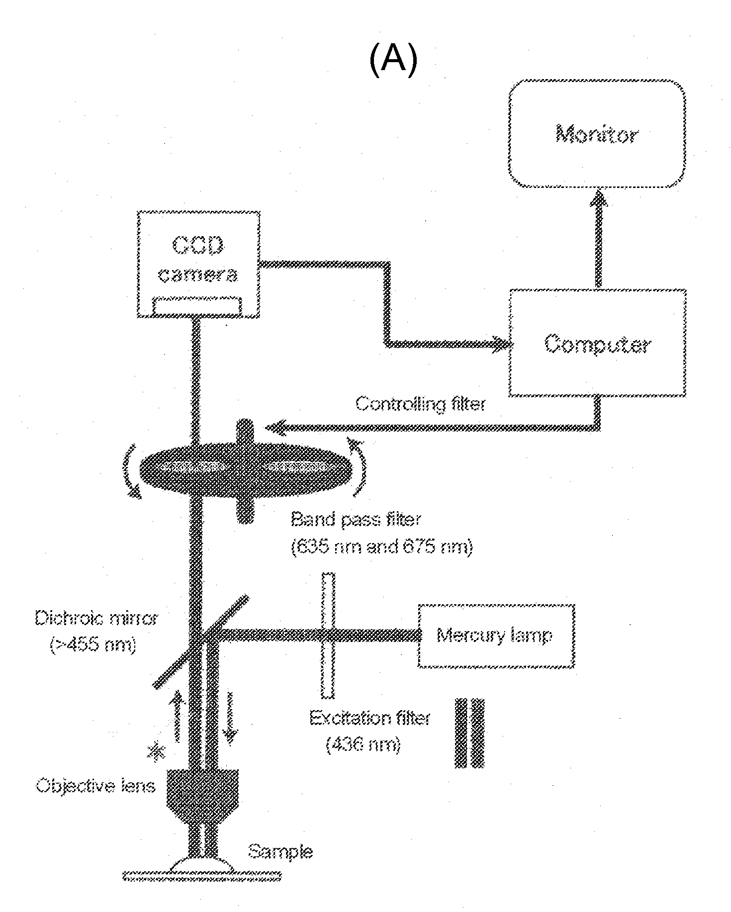
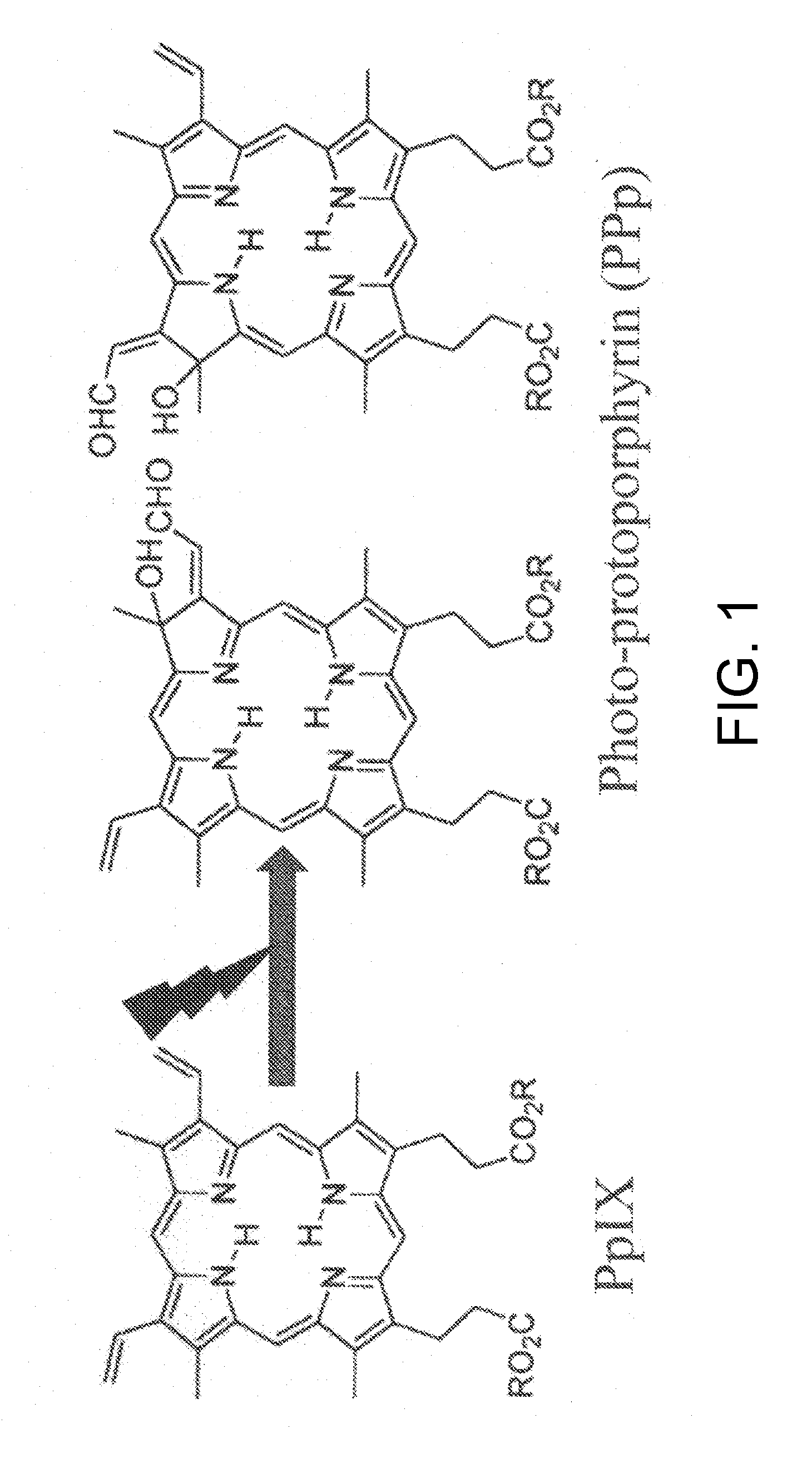
The present invention provides a device for identifying a tumor site in a subject, the device spectroscopically detecting fluorescence of protoporphyrins present in the tumor site,the protoporphyrins being protoporphyrin IX (PpIX) and photo-protoporphyrin (PPp), andthe device comprising:a light irradiation unit that converts part of PpIX into PPp;a spectroscopy unit that separates PpIX fluorescence and PPp fluorescence:a spectroscopy detection unit that detects the relative fluorescence intensity of the PpIX fluorescence and the PPp fluorescence; anda tumor discrimination unit that discriminates between the tumor site and a non-tumor site based on the relative fluorescence intensity of PpIX and PPp.

Description

CROSS-REFERENCE TO RELATED APPLICATIONS[0001]The present application is a continuation application of International Application No. PCT / JP2012 / 066609, filed on Jun. 28, 2012, which claims priority to Japanese Patent Application No. 2011-143709, filed on Jun. 28, 2011. The contents of these applications are incorporated herein by reference in their entirety.TECHNICAL FIELD[0002]The present invention relates to a device and method for identifying a tumor site. The present invention also relates to a device and method for identifying parathyroid gland.BACKGROUND ART[0003]Lymph node metastasis is an important prognostic factor in gastrointestinal cancers, such as gastric cancer and colon cancer. Accurate diagnosis of the presence of lymph node metastasis is essential to determine appropriate treatment for patients.[0004]For example, the necessity of postoperative adjuvant therapy for many gastrointestinal cancers is determined by the presence of lymph node metastasis (NPL 1 and NPL 2). ...

Claims


Application Information

Patent Timeline
IPC IPC(8): A61B5/00
CPCA61B1/00186A61B1/043A61B1/0646A61B5/0071A61B5/0084A61B5/0091A61B5/418A61B5/6847G01N21/6458G01N21/6486G01N2021/6421
Inventor KOIZUMI, NORIAKITAKAMATSU, TETSUROHARADA, YOSHINORIOTSUJI, EIGO
Owner KYOTO PREFECTURAL PUBLIC UNIV CORP
Why Eureka
Eureka Blog
Learn More