
Method for manufacturing an oxide/oxide composite material turbomachine blade provided with internal channels

a composite material and turbomachine technology, applied in the direction of blade accessories, waterborne vessels, machines/engines, etc., can solve the problems of deteriorating the mechanical properties of the blade, unable to machine internal channels in metal blades, and difficult internal channel machining in blades of metal materials

Active Publication Date: 2014-06-12
SN DETUDE & DE CONSTR DE MOTEURS DAVIATION S N E C M A
View PDF11 Cites 44 Cited by
  • Summary
  • Abstract
  • Description
  • Claims
  • Application Information

AI Technical Summary

Benefits of technology

The invention is a method for manufacturing blade made of composite material with improved cooling internal channels, without compromising the strength of the blade. The method involves the use of sacrificial threads that are eliminated to create the channels, which allows for better cooling and improved stability during use. The channels can be shaped in complex ways, and the method also allows for better density at the core of the blade. The cooling channels have a coiled shape that enhances cooling efficiency during use. Evaporation of water from the blade after impregnation makes it easier to mold and dry the blade.

Problems solved by technology

However, machining internal channels in blades of metal material is quite difficult and can only be done on blades that have relatively simple geometries.
In particular, it is not possible to machine internal channels in metal blades that have a twisted shape.
However, it is possible that the blades obtained as such are not satisfactory, as the impregnation of the preform may not be homogeneous, which results in deteriorating the mechanical properties of the blade.
It is indeed difficult to impregnate thick preforms due to the segregation of the alumina, which is able to hinder the access of the slush in the core of the fiber preform.

Method used


Image

  • Method for manufacturing an oxide/oxide composite material turbomachine blade provided with internal channels
  • Method for manufacturing an oxide/oxide composite material turbomachine blade provided with internal channels
  • Method for manufacturing an oxide/oxide composite material turbomachine blade provided with internal channels

Examples


Embodiment Construction

[0010]To do this, the invention has for object a method for manufacturing a composite material turbomachine blade, which comprises a fiber reinforcement densified by a matrix obtained by sintering particles and which has at least one cooling channel, with the method comprising the following successive steps:

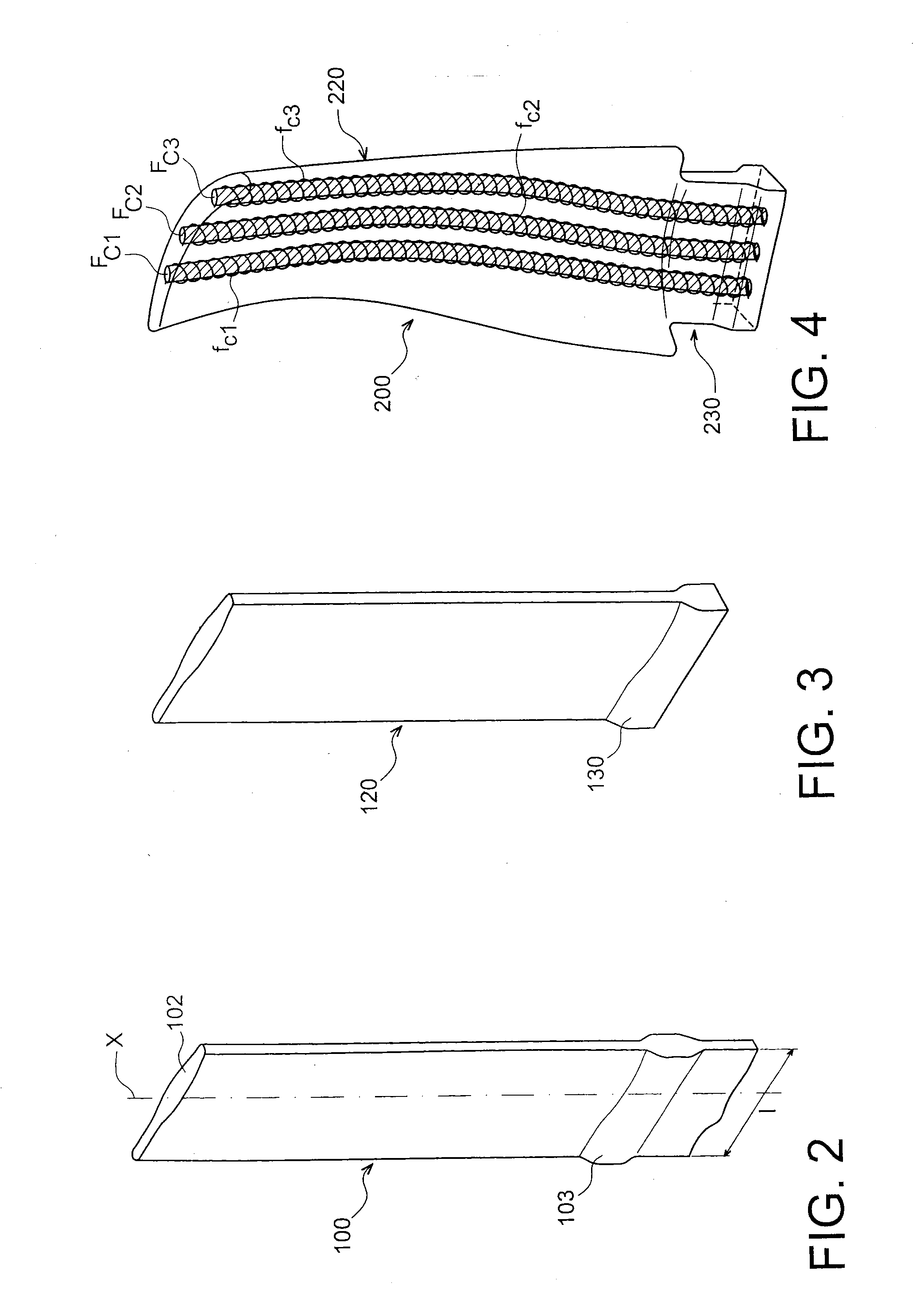
[0011]a) shaping a fiber blank in order to obtain a preform of the blade to be manufactured, the fiber blank comprising a first plurality of threads and a second plurality of threads woven together, with the threads of the first plurality of threads being arranged in successive layers and extending in the longitudinal direction of the fiber blank which corresponds to the longitudinal direction of the blade to be manufactured, at least one layer of threads of the first plurality of threads located in the internal portion of the fiber blank comprising one or several threads made of a first sacrificial material and at least one thread made of a first sacrificial material being surro...


PUM

PropertyMeasurementUnit
temperatureaaaaaaaaaa
melting temperatureaaaaaaaaaa
temperatureaaaaaaaaaa

Abstract

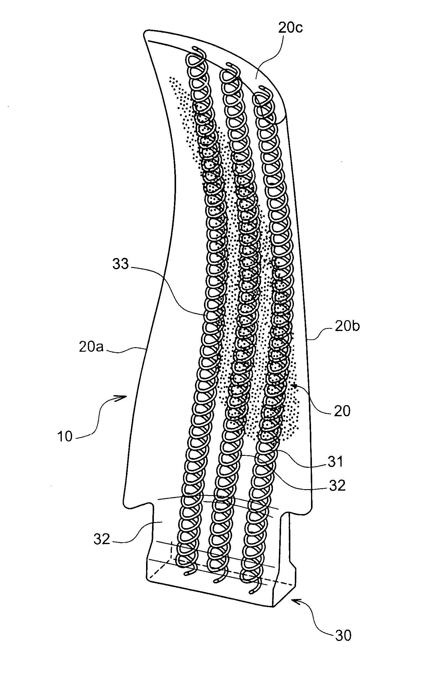
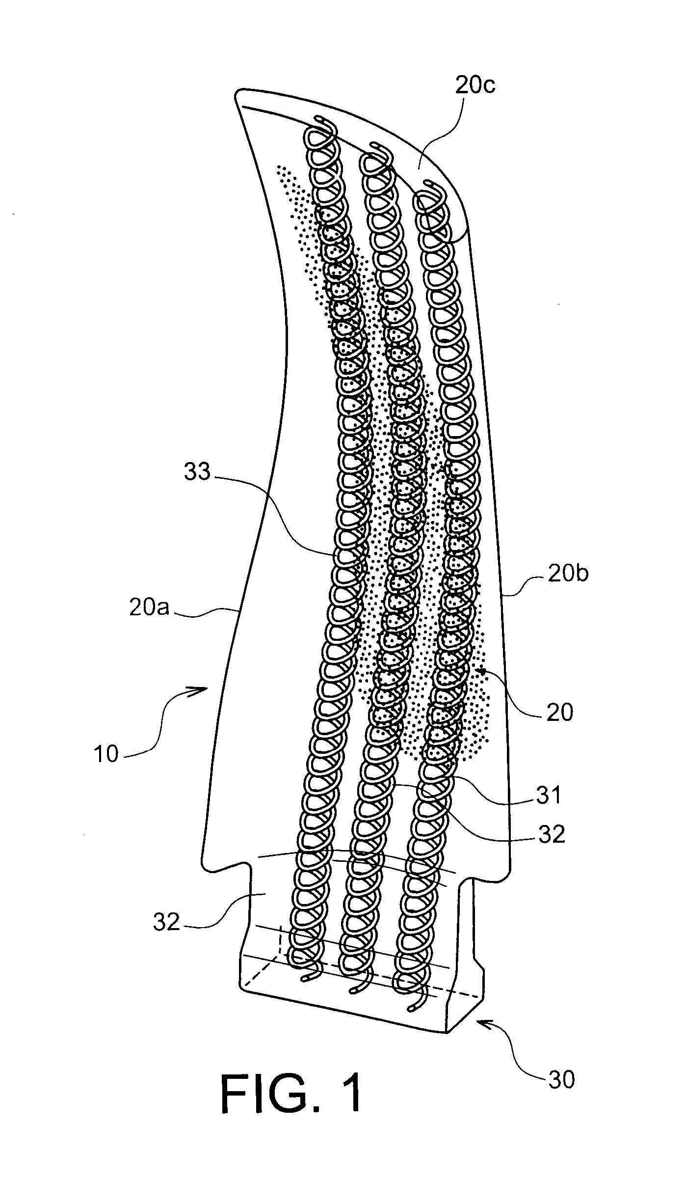
An oxide / oxide composite material turbomachine blade including a fiber reinforcement obtained by weaving a first plurality of threads and a second plurality of threads, with the threads of said first plurality of threads being arranged in successive layers and extending in the longitudinal direction of the fiber blank corresponding to the longitudinal direction of the blade is disclosed. The reinforcement is densified by a matrix, with the blade further including one or several internal channels having a coiled shape extending in the longitudinal direction of the blade.

Description

TECHNICAL FIELD[0001]The invention relates to turbomachine blades provided with internal channels.[0002]More precisely, the invention relates to a method for manufacturing an oxide / oxide ceramic matrix composite material turbomachine blade, provided with one or several internal channels used to cool the blade.PRIOR ART[0003]In order to reduce noise and turbulences at the blade root, it is known to make internal channels within the blades, which channels open out in the vicinity of the root and of the tip of the blade and which allow for the circulation of air.[0004]The blades provided with these internal channels are generally made of a metal material, with the internal channels being hollowed out in the mass of the blade. However, machining internal channels in blades of metal material is quite difficult and can only be done on blades that have relatively simple geometries. In particular, it is not possible to machine internal channels in metal blades that have a twisted shape.[000...

Claims


Application Information

Patent Timeline
Patent Type & Authority Applications(United States)
IPC IPC(8): F01D5/18F01D5/28C04B35/64
CPCF01D5/18F01D5/282C04B35/64F05D2250/15C04B35/62873C04B35/62876C04B2235/3217C04B2235/5212C04B2235/5216C04B2235/5224C04B2235/5248C04B2235/616C04B2235/661F05D2250/25F01D5/187C04B2235/6028C04B35/117C04B35/80B29B11/16B29C70/24B29C70/48F01D5/284
Inventor PODGORSKI, MICHAELDAMBRINE, BRUNO JACQUES, GERARDMOLLIEX, LUDOVIC EDMOND, CAMILLEMEREAUX, BERYL CASSANDRE, ANNE
Owner SN DETUDE & DE CONSTR DE MOTEURS DAVIATION S N E C M A
Learn More